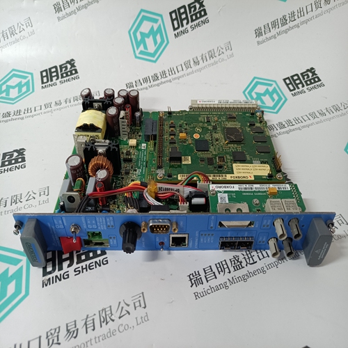
Home > Product > Gas turbine system > 8610-FT-NA Industrial gas turbine module
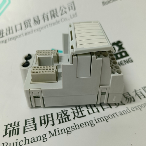
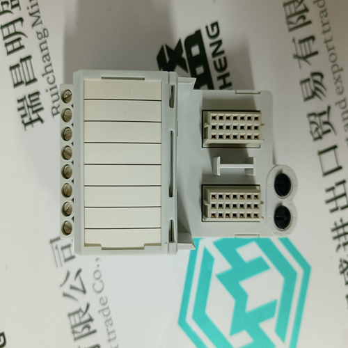
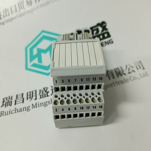
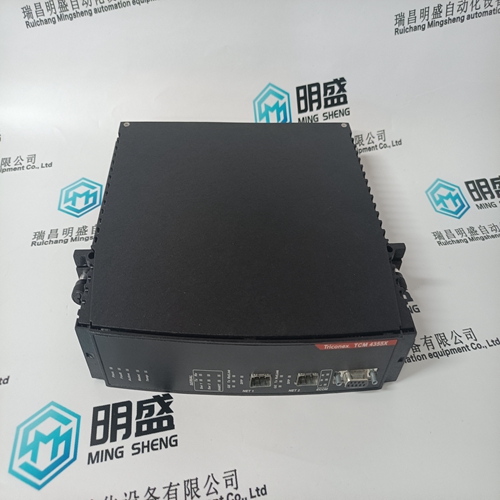
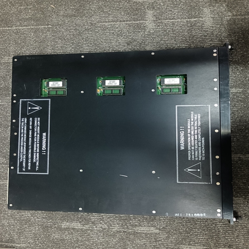
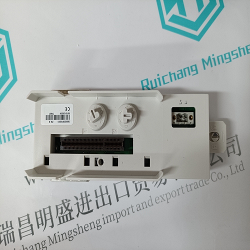
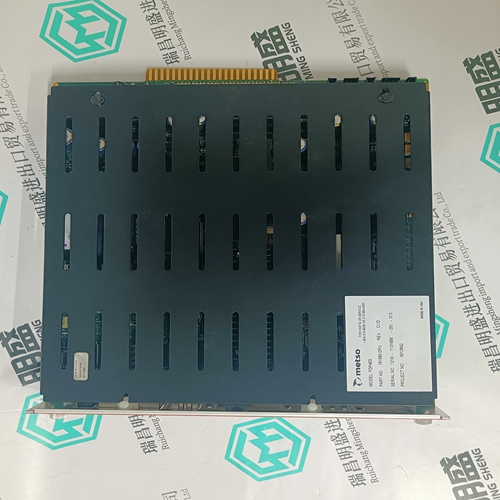
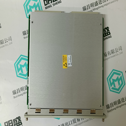
8610-FT-NA Industrial gas turbine module
- Product ID: 8610-FT-NA
- Brand: GE
- Place of origin: the United States
- Goods status: new/used
- Delivery date: stock
- The quality assurance period: 365 days
- Phone/WhatsApp/WeChat:+86 15270269218
- Email:stodcdcs@gmail.com
- Tags:8610-FT-NAIndustrial gas turbine module
- Get the latest price:Click to consult
The main products
Spare parts spare parts, the DCS control system of PLC system and the robot system spare parts,
Brand advantage: Allen Bradley, BentlyNevada, ABB, Emerson Ovation, Honeywell DCS, Rockwell ICS Triplex, FOXBORO, Schneider PLC, GE Fanuc, Motorola, HIMA, TRICONEX, Prosoft etc. Various kinds of imported industrial parts
8610-FT-NA Industrial gas turbine module
An Advant Fieldbus 100 is build up by segments to its full length. The max length of each segment is based of the electrical attenuation of the media of the segment. This is to ensure that the attenuation do not reach that limit, where it may be impossible for the receiver to read the transmitted information with 100% security because of the attenuation in the media. • RG59 Coaxial cable, up to 300 m (1,000 ft.) per segment • RG11 Coaxial cable, up to 700 m (2,300 ft.) per segment • Twisted pair cable, up to 750 m (2,500 ft.) per segment, Communication media according to IEC 1158-2 fieldbus standard. • Optical fibre up to 1700 m (5,500 ft.) per segment
Configuration rules for Coaxial media • Max. cable length: – 300 meter (1,000 ft.) if coaxial cable type RG59 is used. – 700 meter (2,300 ft.) if coaxial cable type RG11 is used. • Max. length of Drop cable: 0.3 meter (1 ft.) • Max. number of nodes: 80. 2.8.1.4 Segments - Minimum Length for Coaxial Media For coaxial media the minimum cable length between two stations is 3 meters (10 ft). For connection between two redundant communication interfaces, within a redundant CI522 or CI630 pair, a distance down to 0,1 meter is allowed provided the distance to the next communication interface is 3 meters or more. NOTE There is no minimum required distance between nodes if: • the bus-cable is connected directly to the device (that is no drop-cable). • the total cable length < 10 meter (30 ft.). • there are only two nodes on the bus.
Transmission Principles
The transmission of a Cyclic Data Packet (CDPs) is managed through a Scan Table. It contains information about all sending CDPs and when they must be transmitted on the Advant Fieldbus 100. The Scan Table is organized in time-slots of one millisecond, in each of which one or more CDPs may be transmitted. Message transfer is performed in an event driven manner in time-slots which are not fully occupied with CDP communication. In order to make sure that message transfer is possible, 25% (for 2000 meter) respectively 50% (for 8500 and 15000 meter) of the time slots are reserved for this purpose, the grey area in the Figure 2-22 and Figure 2-23below. In Figure 2-22 and Figure 2-23below the time-slots (one millisecond each) are indicated on the horizontal axis, while the time distribution inside the individual time-slots (that is which CDP to send) is indicated on the vertical axis.
In the example four different CDPs are configured. CDP1 has a cycle time of 1 ms, CDP2 has a cycle time of 2 ms, and CDP3 and CDP4 have cycle times of 4 ms. The remaining time is used for message transfer when required, white and grey area in the Figure 2-22 above.
