Home > Product > DCS control system > FOXBORO FBM203c P0922UD Redundant channel card
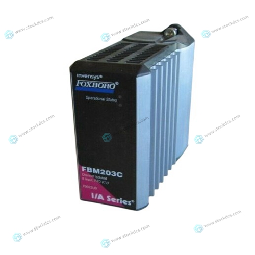
FOXBORO FBM203c P0922UD Redundant channel card
- Product ID: FBM203c P0922UD
- Brand: FOXBORO
- Place of origin: The United States
- Goods status: new/used
- Delivery date: stock
- The quality assurance period: 365 days
- Phone/WhatsApp/WeChat:+86 15270269218
- Email:stodcdcs@gmail.com
- Tags:FOXBOROFBM203cP0922UDRedundant channel card
- Get the latest price:Click to consult
FOXBORO FBM203c P0922UD Redundant channel card
The MVME712B is designed to be used in conjunction with one of the MVME712x modules (MVME712A, MVME712AM, MVME712-12, or MVME712-13). The MVME712x can be connected through the MVME712B to external SCSI devices as shown in Figure 2-9. Because the MVME1xx VMEmodule is at one end of the cable, SCSI terminators are required on the LCP2 adapter. The LCP2 adapter module is shipped with SCSI terminators installed. To install the MVME712B in the system, proceed as follows: 1. Verify that SCSI terminators are installed on the LCP2 adapter module. 2. Install the LCP2 adapter module to the backplane directly in line with the P2 connector on the MVME1xx VMEmodule. Be sure to orient pin 1 of the adapter with pin 1 of the backplane connector. 3. MVME712-12 and MVME712-13: Attach the cable supplied with the MVME712x module from LCP2 adapter connector J2 to connector P2 on the MVME712x module. Be sure to orient cable pin 1 with connector pin 1.
Connect the SCSI INTERFACE cable
on the MVME712B to connector J3 on the LCP2 adapter. 5. Connect the ETHERNET cable on the MVME712B to connector J10 on the MVME712x. 6. Insert the MVME712B module into the selected slot and tighten the attaching screws. 7. Connect a user-supplied cable with compatible pinouts from the SCSI interface on the front panel of the MVME712B to the external SCSI devices. 8. Verify that terminators are installed on the last SCSI device on the cable. If they are not present, install terminators. 9. After making sure you will not pinch cables with the cover, reinstall the cover you previously removed. 10. Connect the power cable to the AC power source and turn the unit on. 11. If SCSI does not work properly, you may have to repair a defective cable and/or replace a blown fuse.
All front panel connectors have metal shells
and jack posts that are electrically connected to the front panel. If the front panel is electrically connected to the chassis ground, then the shells and jack posts are connected to chassis ground. This allows shielded cable to be used for effective reduction of EMI and EMC problems. Connector P2 Interconnect Signals (LCP2 Adapter) Connector P2 on the LCP2 adapter board is a standard DIN 41612 triple-row, 96-pin male connector. Each pin connection, signal mnemonic, and signal characteristic for the connector rows A and C are the same pin-for-pin as connector P2 on the MVME1xx VMEmodule. Row B has only +5 Vdc and ground connected on the LCP2 adapter.

product application
Products are widely used in metallurgy, petroleum, glass, aluminum manufacturing, petrochemical industry, coal mine, papermaking, printing, textile printing and dyeing, mechanical, electronic manufacturing, automobile manufacturing, plastic machinery, electric power, water conservancy, water treatment/environmental protection, boiler heating, energy, power transmission and distribution and so on
Superior products
--ABB Accuray
--ABB Advant OCS
--ABB Advant-800xA
--ABB H&B Contrans T
--ABB H&B Freelance 2000
--Allen Bradley PLC
--GE Ran card machine accessories,PLC
--ICS Triplex Rockwell T8151B/T8461/T8310
--Triconex/Foxboro:3625/3721/3503E/FBM237/FBM242
--Emerson:CE3008/VE3008/SE3008/A6120/A6312
--Motorola:MCP750/MVME162/MVME2604/MVME5100
--Woodward:9907-164/9907-167/9905-144/9905-018
The company is mainly engaged in above brands. You are welcome to inquire from me via email!