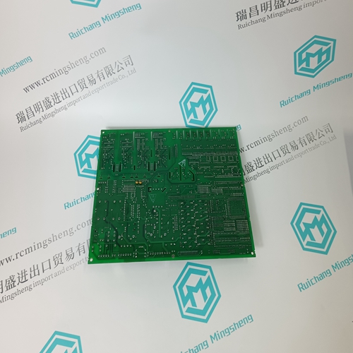
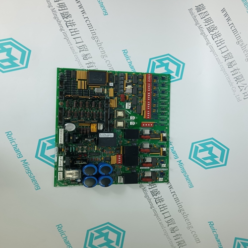
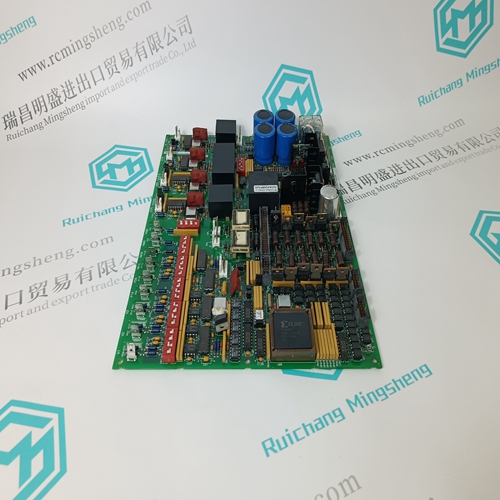
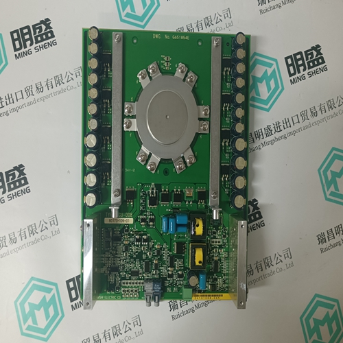
Home > Product > PLC programmable module > DS200DCFBG1BNC Gas turbine module
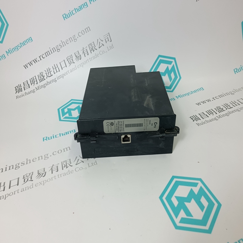
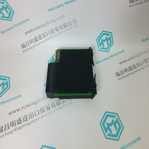
DS200DCFBG1BNC Gas turbine module
- Product ID: DS200DCFBG1BNC
- Brand: GE
- Place of origin: the United States
- Goods status: new/used
- Delivery date: stock
- The quality assurance period: 365 days
- Phone/WhatsApp/WeChat:+86 15270269218
- Email:stodcdcs@gmail.com
- Tags:DS200DCFBG1BNCGas turbine module
- Get the latest price:Click to consult
The main products
Spare parts spare parts, the DCS control system of PLC system and the robot system spare parts,
Brand advantage: Allen Bradley, BentlyNevada, ABB, Emerson Ovation, Honeywell DCS, Rockwell ICS Triplex, FOXBORO, Schneider PLC, GE Fanuc, Motorola, HIMA, TRICONEX, Prosoft etc. Various kinds of imported industrial parts
DS200DCFBG1BNC Gas turbine module
11.3 TROUBLESHOOTING Troubleshooting the controller is primarily done by error codes. Error codes are indicated on the alphanumeric display in response to a failed power-up diagnostic test or to an on-line controller error. Section 11.4 provides a quick reference to the identification of these codes and discusses each code with respect to the type of test or error check, controller response, problem confirmation, and corrective action. In the event a malfunction within the controller is suspected, troubleshooting by assembly substitution is recommended to get the controller back on-line in the shortest possible time. The plug-in design of controller assemblies permits rapid removal and replacement to isolate a defect. Figure 11-1 shows controller assemblies. If a problem appears upon initial installation of the controller, check the installation wiring and the controller’s configuration parameters. Also, check the wiring of associated external process devices (e.g. process transmitter, LonWorks modules). Field servicing experience indicates that most initial service incidents are of this nature. Additional troubleshooting avenues are also possible. For example, a series of test configurations may be created and implemented to ‘exercise’ different function blocks within the controller. Section 3 describes each function block. This type of troubleshooting analysis is intended to be implemented in an off-line test bench situation. On-line checks of the controller input and output signals (i.e. analog and digital) can be performed without affecting station operation. However, this type of signal tracing is usually carried out behind an instrument panel. Refer to the Installation section, Table 8.1, for rear terminal assignments.
MPU CONTROLLER BOARD JUMPERS
There are two Controller board versions. Figure 11-2 shows an MPU Controller board with jumpers W2, W4 and W8. Figure 11-3 shows an MPU Controller board with jumpers W2, W4, and W7. These jumpers are factory set but may need to be changed in the field. W2 and W4 are discussed in Section 11.5.5 Accessory Boards. W7 and W8 settings are described in the figures and in Section 11.5.3 MPU Controller Board. ETHERNET BOARD LED’s The board has 5 green LEDs and one red LED18. Green LEDs announce status and the red LED flashes to indicate an error code. LEDs are visible after freeing the Display Assembly and holding it slightly to one side of the case. The LEDs are: • ACT - Flashes when there is Ethernet activity. It glows steadily when there is an Ethernet connection but no activity and extinguishes when there is no Ethernet connection. • F/H - Lighted for Full duplex and off for Half duplex. • 100 - Lighted for 100 MB network and off for 10 MB network • ST - Lighted during Self-Test and off in normal operation. • Modbus - When lighted, the green LED indicates an operating Modbus board. The red LED will normally be off. When an error exists, the red LED will flash one second on/one second off with a 5 second pause. Count the number of flashes between two pauses. 1 flash - Data bus test failure 2 flashes - Address bus test failure 3 flashes - Data read/write test failure 4 flashes - Register 40001 test failure 5 flashes - Register 40070-40077 test failure 6 flashes - Flash CRC test failure The board is not user serviceable.
