Home > Product > DCS control system > TRICONEX DI6503 Channel relay card
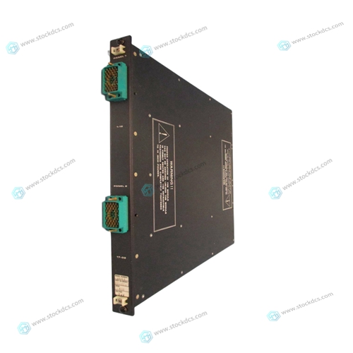
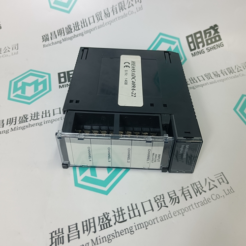
TRICONEX DI6503 Channel relay card
- Product ID: DI6503
- Brand: TRICONEX
- Place of origin: The United States
- Goods status: new/used
- Delivery date: stock
- The quality assurance period: 365 days
- Phone/WhatsApp/WeChat:+86 15270269218
- Email:stodcdcs@gmail.com
- Tags:TRICONEXDI6503Channel relay card
- Get the latest price:Click to consult
TRICONEX DI6503 Channel relay card
To configure port 1 for DTE (terminal to modem) operation, remove jumpers from header J1 and install jumpers on header J11 as shown below. This is the default configuration as shipped from the factory.To configure port 2 for DCE (modem to terminal) operation, install jumpers on header J16 and remove jumpers from header J17 as shown below.You must ensure that the SCSI bus is terminated properly. The P2 adapter and the MVME712M module have sockets for terminating the SCSI lines. Both the P2 adapter and the MVME712M use three 8-pin SIP resistors. Refer to the installation instructions for use of the terminators.
Preparing the P2 Adapter Board
The P2 adapter board is required. Preparation of the P2 adapter consists of removing or replacing the terminating resistors for SCSI. Figure 2-11 shows the component locations. Refer to the installation instructions in Installing the MVME712M, in this chapter, for use of the terminators. A P2 mounting bracket kit is also furnished for use on some systems.The MVME712M front panel has four serial ports, one printer port, one SCSI port, and one Ethernet port. The connectors for these ports, the P2 backplane connector, and two modem connectors are described in the following table. The P2 adapter board’s MVME712M connector, P2 connector, and SCSI connector are also described in the table. Cables recommended for use with the connectors are also listed in the table. Note that not all peripheral cables needed are provided with the MVME712M. You may need to fabricate or purchase certain cables
Preparing and Installing the Hardware
User-supplied 20-conductor cable; usually supplied with the modem If you wish to use your own cable for the P2 signals from J2 on the P2 adapter board to J2 on the MVME712M, note that the cable should be kept as short as possible. Any cable over 2.5 to 3 feet is likely to cause signal problems. The maximum cable length that can be used from the P2 adapter board to the MVME712M will vary depending on what other cables are attached to the MVME712. The connections most susceptible to problems caused by long P2 cables are the Ethernet and parallel port connections.

product application
Products are widely used in metallurgy, petroleum, glass, aluminum manufacturing, petrochemical industry, coal mine, papermaking, printing, textile printing and dyeing, mechanical, electronic manufacturing, automobile manufacturing, plastic machinery, electric power, water conservancy, water treatment/environmental protection, boiler heating, energy, power transmission and distribution and so on
Superior products
--ABB Accuray
--ABB Advant OCS
--ABB Advant-800xA
--ABB H&B Contrans T
--ABB H&B Freelance 2000
--Allen Bradley PLC
--GE Ran card machine accessories,PLC
--ICS Triplex Rockwell T8151B/T8461/T8310
--Triconex/Foxboro:3625/3721/3503E/FBM237/FBM242
--Emerson:CE3008/VE3008/SE3008/A6120/A6312
--Motorola:MCP750/MVME162/MVME2604/MVME5100
--Woodward:9907-164/9907-167/9905-144/9905-018
The company is mainly engaged in above brands. You are welcome to inquire from me via email!