Home > Product > DCS control system > TRICONEX ICM6211 Overspeed detection card
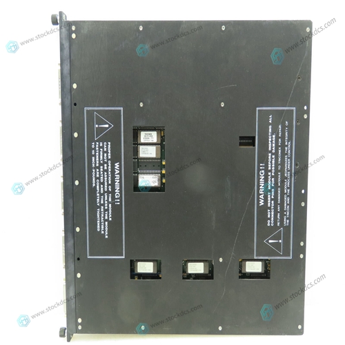
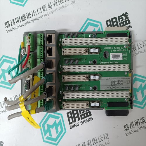
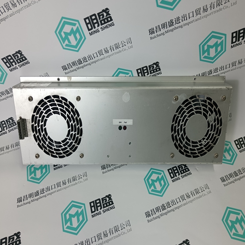
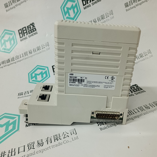
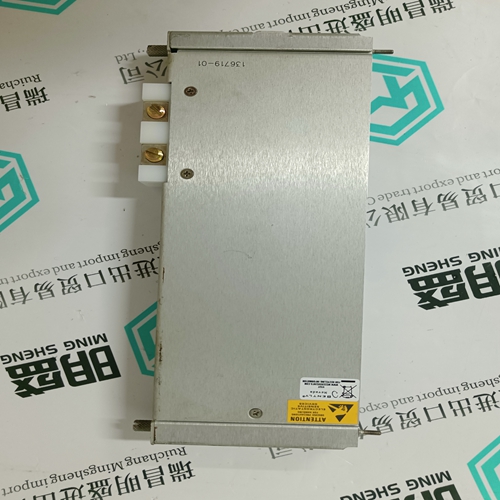
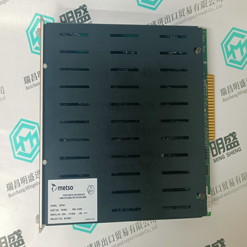
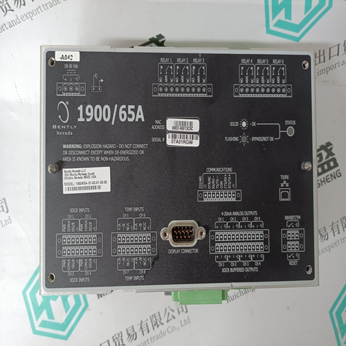
TRICONEX ICM6211 Overspeed detection card
- Product ID: ICM6211
- Brand: TRICONEX
- Place of origin: The United States
- Goods status: new/used
- Delivery date: stock
- The quality assurance period: 365 days
- Phone/WhatsApp/WeChat:+86 15270269218
- Email:xiamen2018@foxmail.com
- Tags:TRICONEXICM6211Overspeed detection card
- Get the latest price:Click to consult
TRICONEX ICM6211 Overspeed detection card
The MVME712M can be connected in different configurations. The installation procedure begins on this page, and continues using the instructions given for one of the configurations listed in Table 2-2. Motorola strongly recommends that you use an antistatic wrist strap and a conductive foam pad when installing or upgrading the system. Electronic components, such as disk drives, computer boards, and memory modules, can be extremely sensitive to ESD. After removing the component from the system or its protective wrapper, place the component flat on a grounded, static-free surface, and in the case of a board, component-side up. Do not slide the component over any surface. If an ESD station is not available, you can avoid damage resulting from ESD by wearing an antistatic wrist strap (available at electronics stores) that is attached to an unpainted metal part of the system chassis.
Procedure
To begin the installation of the MVME712M in the system, proceed as follows: 1. Turn all equipment power OFF and disconnect the power cable from the AC power source. 2. Remove the chassis cover as instructed in the equipment user’s manual 3. Remove the filler panel(s) from the appropriate card slot(s) at the rear of the chassis (if the chassis has a rear card cage). Other modules in the unit may have to be moved to allow space for the cables connected to the P2 adapter and the MVME712M. 4. Continue the installation procedure by choosing one of the configurations listed in the following table, and described on the following pages. Note that the designations A through F are used solely as convenient references.
Internal SCSI Devices Only
1. The MVMExxxx is at one end of the cable, so terminators must be installed on the P2 adapter module. 2. Install the P2 adapter module to the backplane directly in line with the P2 connector on the MVMExxxx. Be sure to orient pin 1 of the adapter with pin 1 of the backplane connector. 3. Connect a user-supplied 50-conductor cable with compatible pinouts from connector J3 on the P2 adapter to the internal SCSI devices. 4. Terminators must be installed on the last SCSI device in the system. 5. Attach the furnished 64-conductor cable from connector J2 on the P2 adapter to connector J2 on the MVME712M. Be sure to orient cable pin 1 with connector pin 1. 6. Insert the MVME712M module into the selected slots and tighten the attaching screws, making good contact with the transverse mounting rails to minimize RF emissions.


product application
Products are widely used in metallurgy, petroleum, glass, aluminum manufacturing, petrochemical industry, coal mine, papermaking, printing, textile printing and dyeing, mechanical, electronic manufacturing, automobile manufacturing, plastic machinery, electric power, water conservancy, water treatment/environmental protection, boiler heating, energy, power transmission and distribution and so on
Superior products
--ABB Accuray
--ABB Advant OCS
--ABB Advant-800xA
--ABB H&B Contrans T
--ABB H&B Freelance 2000
--Allen Bradley PLC
--GE Ran card machine accessories,PLC
--ICS Triplex Rockwell T8151B/T8461/T8310
--Triconex/Foxboro:3625/3721/3503E/FBM237/FBM242
--Emerson:CE3008/VE3008/SE3008/A6120/A6312
--Motorola:MCP750/MVME162/MVME2604/MVME5100
--Woodward:9907-164/9907-167/9905-144/9905-018
The company is mainly engaged in above brands. You are welcome to inquire from me via email!
