Home > Product > DCS control system > TRICONEX 3704E control module
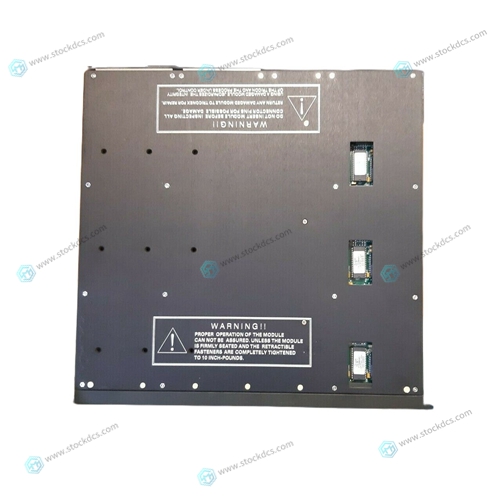
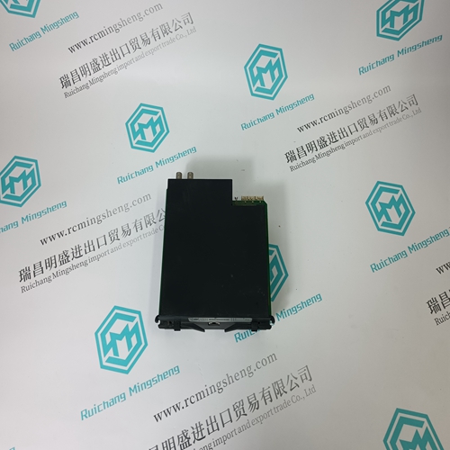
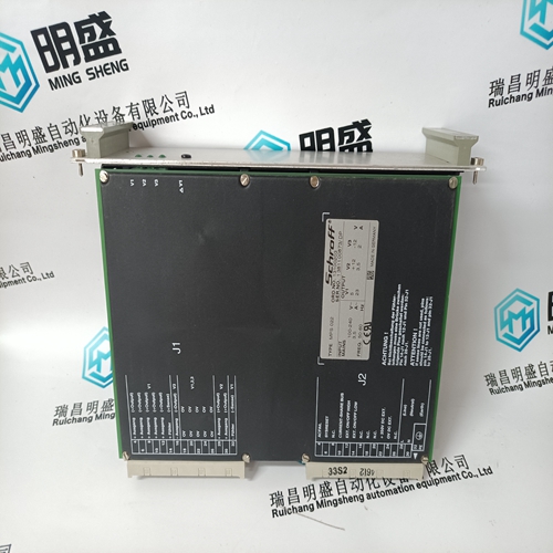
TRICONEX 3704E control module
- Product ID: 3704E
- Brand: TRICONEX
- Place of origin: The United States
- Goods status: new/used
- Delivery date: stock
- The quality assurance period: 365 days
- Phone/WhatsApp/WeChat:+86 15270269218
- Email:stodcdcs@gmail.com
- Tags:TRICONEX3704Econtrol module
- Get the latest price:Click to consult
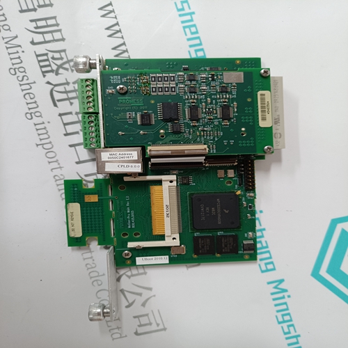
TRICONEX 3704E control module
The Reflective Memory Board upon power-up is able to establish the board-to-board link without any program setup. The Bus Interrupter Module (BIM) which controls the interrupt generation on the Reflective Memory Board is initialized to mask all interrupts upon power-up. If interrupts are desired, the appropriate registers in the BIM chip must be initialized through software control. A CSR is also present on the board which controls the Fail LED on the Reflective Memory Board. The user must Write to the CSR after any test software is run successfully on the board in order to turn OFF the Fail LED. There is no automatic diagnostic software on the board to perform self-test function so the LED being ON does not indicate a failure on-board unless the VME chassis software control actually has turned it ON. LED ON is a standard power-up mode for the Fail LED. If the output FIFO becomes over half full, the Reflective Memory Board will issue an interrupt if the BIM has been programmed and enabled.
Hardware Requirements to Use Reflective
Memory Board Aside from the address map decoding required on the Reflective Memory Board there are a few system jumpering requirements which must be followed to allow the system to work. The first requirement is that each Reflective Memory Board on the communications bus must have a unique node ID address (jumperselectable on-board). No two nodes can share the same node number, i.e., 0,1...255. Nodes may be intermixed in any order as far as unique board IDs are concerned. There is parity and other error checking hardware on the link so the Reflective Memory Board will inform the user if an improper condition in the link exists. Each Reflective Memory Board may be mapped into a different address space. Data will appear in the same location in each node relative to the base 1 Mbyte boundry each Reflective Memory is mapped to
There is a restriction on address configuration
relating to each 1 Mbyte boundary for the 512 K and 256 K option Reflective Memory Boards. Even though the 512 K option may be mapped on any 512 K boundary, relative to the 1 Mbyte boundaries, there is an upper and a lower position (see Figure 3.5-1). All boards must be mapped to the same position relative to 1 Mbyte boundaries. There are four positions possible with the 256 K Reflective Memory Boards relative to 1 Mbyte boundaries. All 256 K boards on the link must be mapped to the same position relative to the 1 Mbyte boundaries in order to communicate. There is no restriction between which 1 Mbyte boundary each board is on. Exact address matching is not required; only the position relative to the nearest 1 Mbyte boundary must be the same.

Superior products
Main products include DCS control system spare parts, PLC system spare parts and robot system spare parts,Advantage brands: Allen Bradley, BentlyNevada, ABB, Emerson Ovation, Honeywell DCS, Rockwell ICS Triplex, B&R, FOXBORO, Schneider PLC, GE Fanuc, Motorola, HIMA, TRICONEX, Prosoft and other imported industrial parts
Application industry
Our main products are widely used in metallurgy, oil and gas, glass manufacturing, aluminum, petrochemical, coal mine, paper making and printing, textile printing and dyeing, machinery, electronic manufacturing, automobile manufacturing, tobacco, plastic machinery, electricity, water conservancy, water treatment/environmental protection, municipal engineering, boiler heating, energy, power transmission and distribution, etc.