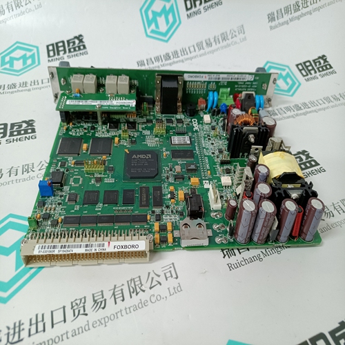
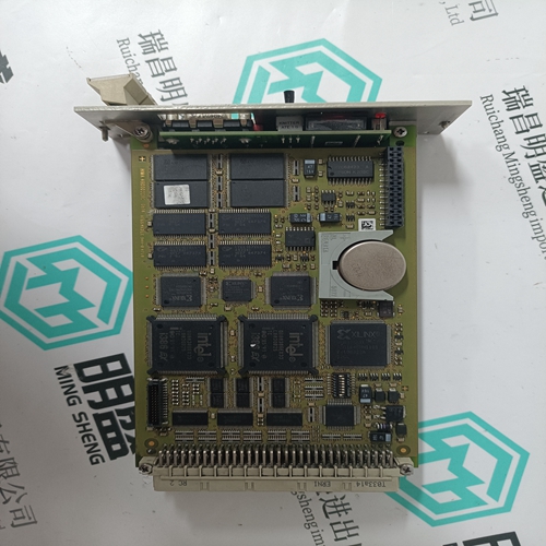
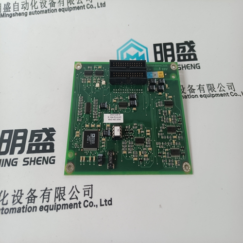
Home > Product > DCS control system > TRICONEX 8306A Power module
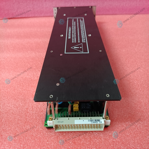
TRICONEX 8306A Power module
- Product ID: 8306A
- Brand: TRICONEX
- Place of origin: The United States
- Goods status: new/used
- Delivery date: stock
- The quality assurance period: 365 days
- Phone/WhatsApp/WeChat:+86 15270269218
- Email:stodcdcs@gmail.com
- Tags:TRICONEX8306APower module
- Get the latest price:Click to consult
TRICONEX 8306A Power module
Input Buffers, Analog Multiplexers, a Programmable Amplifier and a 16-bit A/D Converter digitize the analog input channels. The digitized values are stored in a dual-ported data buffer for access from the VMEbus. Optional low pass input filters minimize the effects of system noise and eliminate high frequency signal components which would otherwise cause accuracy problems. Input Buffers eliminate the error associated with varying source resistance. The scan rate is selectable from 381 Hz to 100 kHz for high-performance mode, and 381 Hz to 50 kHz for standard performance mode according to the scan rate equations in the Rate Control Register (RCR) on page 64. Operating modes are described in detail in Operating Modes on page 75. Regulated ±15 VDC power for the analog networks is obtained from the 5 VDC bus through a DC-to-DC Converter.
A separate gain buffer permits
the input gain of each channel to be assigned individually. Gain codes ($0 = x1, $1 = x10) are first loaded into the gain buffer from the bus, and the gain for each channel is then used during the scanning process. A fixed gain for all channels can also be software programmed if programmable gain per channel is not required. Control signals and data transfers take place through the VMEbus P1 and P2 connectors. VMEbus Interface Logic controls data transfers through the P1 and P2 interface, and latches the operating mode parameters. Status monitoring and sequence timing are supported by a Bus Interrupter and Programmable Timer, both of which are controlled from the bus. Scan timing logic controls the analog input scanning process, uses the gain buffer to adjust input gain, sets the sampling rate, and routes digitized channel data to the data buffer
Board Selection
VMEbus data transfer requests are accepted when the Board-Selection Comparator detects a match between the on-board selection jumpers shown in Figure 1-1 on page 21, and the address and address modifier lines from the backplane. When a match is detected, the board responds with a data transfer, after which the open collector DTACK interface signal is asserted (LOW). DTACK returns to the negated (HIGH) state when the transfer has been completed. During an interrupt response, DTACK is provided by the interrupt controller


Superior products
Main products include DCS control system spare parts, PLC system spare parts and robot system spare parts,Advantage brands: Allen Bradley, BentlyNevada, ABB, Emerson Ovation, Honeywell DCS, Rockwell ICS Triplex, B&R, FOXBORO, Schneider PLC, GE Fanuc, Motorola, HIMA, TRICONEX, Prosoft and other imported industrial parts
Application industry
Our main products are widely used in metallurgy, oil and gas, glass manufacturing, aluminum, petrochemical, coal mine, paper making and printing, textile printing and dyeing, machinery, electronic manufacturing, automobile manufacturing, tobacco, plastic machinery, electricity, water conservancy, water treatment/environmental protection, municipal engineering, boiler heating, energy, power transmission and distribution, etc.
