Home > Product > DCS control system > TRICONEX 9001 Drive input card
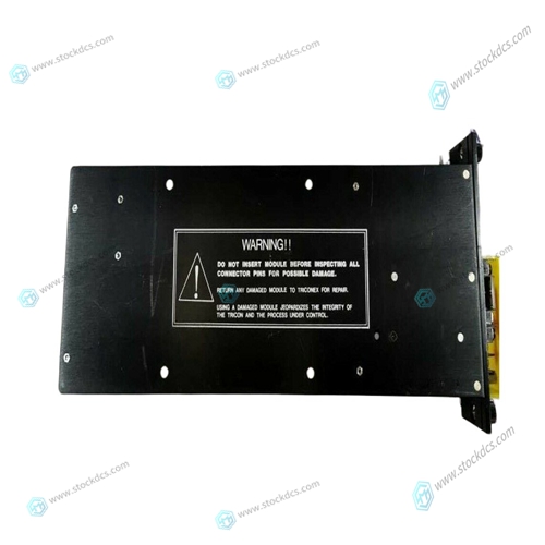
TRICONEX 9001 Drive input card
- Product ID: 9001
- Brand: TRICONEX
- Place of origin: The United States
- Goods status: new/used
- Delivery date: stock
- The quality assurance period: 365 days
- Phone/WhatsApp/WeChat:+86 15270269218
- Email:stodcdcs@gmail.com
- Tags:TRICONEX9001Drive input card
- Get the latest price:Click to consult
TRICONEX 9001 Drive input card
Software Trigger - This mode is selected by clearing both trigger mode control bits in the CSR. With both bits cleared, a write command to the Software Trigger Command register located at relative address $000E causes the selected scan mode to begin. External Trigger - This mode is selected by clearing trigger mode bit 13 and setting trigger mode bit 12. This enables the board to accept an external trigger. Upon receiving the external trigger, the selected scan mode is initiated. Interval Timer Trigger - This mode is selected by setting bit 13 and clearing bit 12. This setting enables the interval timer and the selected scan mode is initiated each time the timer programmed time interval expires.
Autoscan
Selected by clearing both scan mode control bits in the CCR and is the default selection after a reset operation. All active channels are scanned continuously in this mode. Single Scan - Selected by clearing scan mode control bit 7 and setting bit 6. All active channels are scanned through once, and the scan process is stopped until the next trigger event. Random Access - Selected by setting bit 7 and letting bit 6 be a Don’t Care. In this mode, a channel is selected by entering the channel number in bits D05-D00 in the CCR. This desired channel is sampled, digitized and stored at RAM offset address $0080.
Input Configuration
Analog inputs from connectors P3 and P4 are routed through low pass Input Filters and OP AMP Buffers to the input multiplexers shown in Figure 1-2 on page 25. Channels 00 to 31 are connected through P4 and Channels 32 to 63 are connected through P3. To provide at least one ground in each of the input connectors, the LOW inputs for Channels 31 and 63 can be jumpered individually to AGND, or can be left ungrounded (see the “Configuration and Installation” section of this Manual). AGND is the internal analog ground. The center row (B row) pins on connectors P3 and P4 are tied to AGND. This provides a return for all channels if 96-wire ribbon cables are used for the analog inputs. The Analog Multiplexers route one of each group of eight channels to the Programmable Gain Amplifier (PGA) multiplexers, which in turn selects an input to route to the PGA. Input address lines A0 and A1 control the input multiplexer, while A3, A4, and A5 select the PGA multiplexer input. Each input multiplexer has an individual enable signal which enables the multiplexer with the desired channel. Crosstalk and source impedance errors are minimized by the input OP AMP Buffers. The buffers provide a constant low impedance to the multiplexer inputs. Each channel contains a buffer on each input line.

Superior products
Main products include DCS control system spare parts, PLC system spare parts and robot system spare parts,Advantage brands: Allen Bradley, BentlyNevada, ABB, Emerson Ovation, Honeywell DCS, Rockwell ICS Triplex, B&R, FOXBORO, Schneider PLC, GE Fanuc, Motorola, HIMA, TRICONEX, Prosoft and other imported industrial parts
Application industry
Our main products are widely used in metallurgy, oil and gas, glass manufacturing, aluminum, petrochemical, coal mine, paper making and printing, textile printing and dyeing, machinery, electronic manufacturing, automobile manufacturing, tobacco, plastic machinery, electricity, water conservancy, water treatment/environmental protection, municipal engineering, boiler heating, energy, power transmission and distribution, etc.