Home > Product > DCS control system > ABB LDMUI-01 3AFE61320946P0001 Adjustment control module
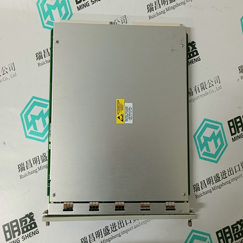
ABB LDMUI-01 3AFE61320946P0001 Adjustment control module
- Product ID: LDMUI-01 3AFE61320946P0001
- Brand: ABB
- Place of origin: The Swiss
- Goods status: new/used
- Delivery date: stock
- The quality assurance period: 365 days
- Phone/WhatsApp/WeChat:+86 15270269218
- Email:stodcdcs@gmail.com
- Tags:ABBLDMUI-013AFE61320946P0001Adjustment control module
- Get the latest price:Click to consult
ABB LDMUI-01 3AFE61320946P0001 Adjustment control module
This procedure tests the Programmable Gain Amplifier (PGA), and verifies the integrity of all input channels. Steps a through e are identical to steps a through e in the Calibration Section, and can be omitted if the calibration procedure has been performed within the previous hour, and if power has not been removed from the board. a. Restore all program jumpers to the factory configuration, as shown in Table 2-1 on page 29. b. Locate the board at an address that is compatible with the VMEbus operating system. c. Install the VMIVME-3122 board on an extender board in the VMEbus chassis. d. Apply power to the chassis backplane. Allow a minimum warm-up interval of ten minutes before proceeding. e. Connect the digital voltage source to the channel 00 input pins P4-A1 (+) and P4-C1 (-). Using a connector that shorts the “B” row to the “C” row, adjust voltage source output to 0.0000 VDC.
Input Modes
Analog inputs are connected to the board through front panel connectors P3 and P4. P4 contains the input pins for Channels 00 to 31, and P3 contains the input pins for Channels 32 to 63. Pin assignments for P3 and P4 are summarized in Table 2-7 on page 43 and Table 2-8 on page 44. The center “B” rows in P3 and P4 are connected together to AGND bus, which can be used as a guard bus for 96-wire cables. Refer to the Calibration Section and Table 2-5 on page 36 for the selection of single-ended or differential input configurations.
Input Cables
If 96-wire 0.033-inch ribbon cables or discrete wire type cables are used for the analog inputs, the center row can provide a ground reference to the analog return (AGND) on the board by installing Jumper J3. If 64-wire 0.050-inch ribbon cables are used, “VARI TWIST” or equivalent twisted pair cables are recommended to minimize crosstalk and induced noise External TTL-level synchronization triggers are connected to the EXT STRT L input on the P2 connector pinout Table 2-6 on page 42. The EN EXT STRT H output is a flag to the triggering device that the VMIVME-3122 is ready to accept an external trigger. To synchronize multiple VMIVME-3122s together, connect the TRIG OUT H output from the designated “master” board to the EXT STRT L input of all boards to be synchronized to the master.

Superior products
Main products include DCS control system spare parts, PLC system spare parts and robot system spare parts,Advantage brands: Allen Bradley, BentlyNevada, ABB, Emerson Ovation, Honeywell DCS, Rockwell ICS Triplex, B&R, FOXBORO, Schneider PLC, GE Fanuc, Motorola, HIMA, TRICONEX, Prosoft and other imported industrial parts
Application industry
Our main products are widely used in metallurgy, oil and gas, glass manufacturing, aluminum, petrochemical, coal mine, paper making and printing, textile printing and dyeing, machinery, electronic manufacturing, automobile manufacturing, tobacco, plastic machinery, electricity, water conservancy, water treatment/environmental protection, municipal engineering, boiler heating, energy, power transmission and distribution, etc.