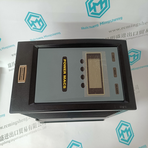
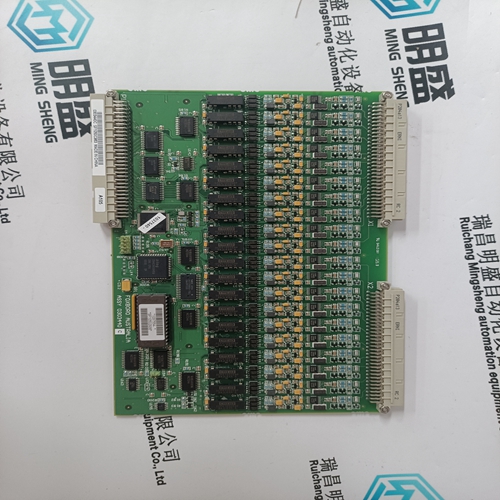
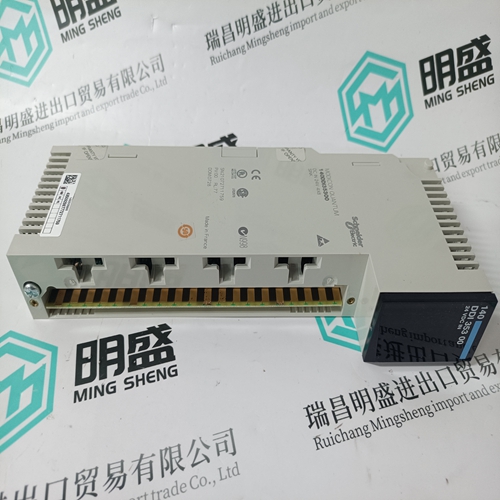
Home > Product > DCS control system > TRICONEX 4351A Channel input module
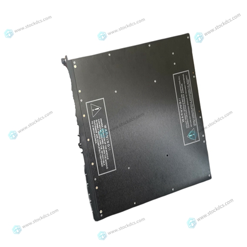
TRICONEX 4351A Channel input module
- Product ID: 4351A
- Brand: TRICONEX
- Place of origin: The United States
- Goods status: new/used
- Delivery date: stock
- The quality assurance period: 365 days
- Phone/WhatsApp/WeChat:+86 15270269218
- Email:stodcdcs@gmail.com
- Tags:TRICONEX4351AChannel input module
- Get the latest price:Click to consult
TRICONEX 4351A Channel input module
Interval timing and data counting capabilities are provided by a triple 16-bit programmable timer/counter (Intel 8254) which is controlled by the Timer/Counter Registers at board addresses $0020 to $0026. Interval Timer Register TR0 is driven by an 6.25 MHz clock, and TR1 is driven by the output of TR0. The Data Counter Register (DCR) operates independently of the two timers, and is used to monitor the progress of data through the buffer. Operating modes and data transfers for all three counters are controlled by the Timer Control Register (TCR). All timer/counter data transfers are 8 bits wide and use data bits D0 to D7. Two data transfers are required to read or write each 16-bit counter, with the least significant byte transferred first and the most significant byte transferred second. The control word determines the type of transfer, and must be written to the timer/counter before each data transfer. Table 3-20 on page 71 lists the data transfer sequences for the timers and counter. Details concerning the Intel 8254 counter and programming requirements can be obtained from Intel. However, the information in this manual should be adequate.
Timer/Counter Registers
The Timer/Counter Registers control three 16-bit counters, two of which are available for adjusting the time between scans in the timed-burst operating mode, and one of which can provide an interrupt at a specific data word count.The Data Counter Register (DCR) can be programmed to provide a data word count directly, or to generate an interrupt when a specific number of A/D conversions have occurred. Table 3-20 on page 71 shows the sequence required for reading the data counter directly. The data counter can be accessed at any time, regardless of which operating mode is selected. Because the counter counts down, the value read is the remaining data count.
Data Counter Register Bit Definitions
Bits 07 through 00: Data Counter Control - The data counter can generate an interrupt after a predetermined number of data words have been stored in the buffer. The counter can be read directly to monitor the data count. To use the counter to generate an interrupt: 1. Load the data counter with the required data count (See Table 3-20 on page 71) 2. Set the source control bit D10 in the CCR (Table 3-23 on page 73) to a one (1). (This disables the Midscan/Endscan interrupt.) 3. Enable the interrupt as described in Section 4.7. 4. Initiate the scanning operation.


Superior products
Main products include DCS control system spare parts, PLC system spare parts and robot system spare parts,Advantage brands: Allen Bradley, BentlyNevada, ABB, Emerson Ovation, Honeywell DCS, Rockwell ICS Triplex, B&R, FOXBORO, Schneider PLC, GE Fanuc, Motorola, HIMA, TRICONEX, Prosoft and other imported industrial parts
Application industry
Our main products are widely used in metallurgy, oil and gas, glass manufacturing, aluminum, petrochemical, coal mine, paper making and printing, textile printing and dyeing, machinery, electronic manufacturing, automobile manufacturing, tobacco, plastic machinery, electricity, water conservancy, water treatment/environmental protection, municipal engineering, boiler heating, energy, power transmission and distribution, etc.
