Home > Product > Robot control system > DECS-200-2L Voltage regulator
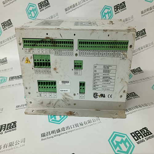
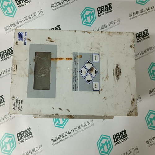
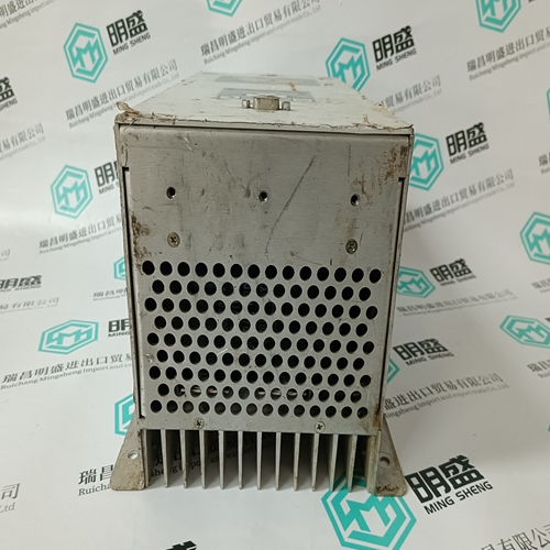
DECS-200-2L Voltage regulator
- Product ID: DECS-200-2L
- Brand: BASLER ELECTRIC
- Place of origin: the United States
- Goods status: new/used
- Delivery date: stock
- The quality assurance period: 365 days
- Phone/WhatsApp/WeChat:+86 15270269218
- Email:stodcdcs@gmail.com
- Tags:DECS-200-2LVoltage regulatorBASLER ELECTRIC
- Get the latest price:Click to consult
The main products
Spare parts spare parts, the DCS control system of PLC system and the robot system spare parts,
Brand advantage: Allen Bradley, BentlyNevada, ABB, Emerson Ovation, Honeywell DCS, Rockwell ICS Triplex, FOXBORO, Schneider PLC, GE Fanuc, Motorola, HIMA, TRICONEX, Prosoft etc. Various kinds of imported industrial parts
DECS-200-2L Voltage regulator
Attention The mounting of the EM 2/6 modules must only take place by DUNGS or by third parties authorised by Dungs. Functions Relay outputs as a function of state: As a function of the program state, the relay contacts are closed or opened. The externally applied voltage is switched to random consumers. Application - Signalling of operational states - Activation of analogue actuators By using analogue actuators, two position messages can be reported to the EM 2/6. PWM signal for activation, for example, of speed-controlled fans.The PWM signal can be modulated during the "operation" state by applying a mains voltage signal. The speed is controlled with no speed feedback. Analogue output for current / voltage The current signal (4-20 mA) or the voltage signal (0-10 VAC) can be modulated by applying a mains voltage signal. Fieldbus communication Profibus DP and modbus interface are integrated into the EM 2/6 extension module. For the description, see page 68 ff. EM 2/4 modul Flame safeguard, shutter activation for continuous operation. The activation of the EM1/1 shutter module, which is necessary for the continuous operation of DUNGS UV 4x and FLW 41I flame safeguards, is integrated into the EM 2/6 (for the description, see page 84).
Parameters
All "speed" values or the like refer to the PWM control signal and have no significance for the actual speed of the fan. The values P240 to P244 can be changed after entry of a password, depending on the access level. Reading access is possible for all parameters, independently of the access level. Parameters P245 to P249 can be changed without password. Parameters can be changed via the VisionBox or the display of the MPA 41x2. Changed parameters are applied to the fan control after no later than 10 s. Indicates the value by which the desired speed of the fan is incremented or decremented. The calculation is carried out 16 times per second, i.e., the value of the parameter is added to or subtracted from the current value in the 1/16 s cycle. The increment in the tables is used for certain positions of the inputs, see D+ and D-.
The parameter value is used for state 8 (pre-venting) of the MPA41xx. Indicates at which time the fan is moved to the ignition position. The value corresponds to the time before the end of preventing (remaining pre-venting state time). NOTE: Must not be greater than the P30 pre-venting time, otherwise fault configuration with restart will be carried out. State 8 (pre-venting) is divided into 3 parts P248 + x+ P248 = P30 (x must be greater than 1 if monitoring is active). After the first High Fire time (P248): State 20 (post-venting) P248 +x = P51 (x must be greater than 1 if monitoring is active). The control of parameters P248, P30 and P50 takes place during the watchdog loading phase. During changes in operation (parameter not monitored), Low/High Fire monitoring can be disabled if P248 ≤ P50.
