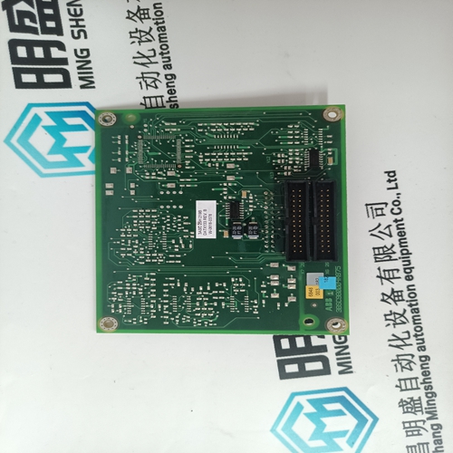
Home > Product > DCS control system > 5SHY3545L0009 3BHB013085R0001 Thyristor module
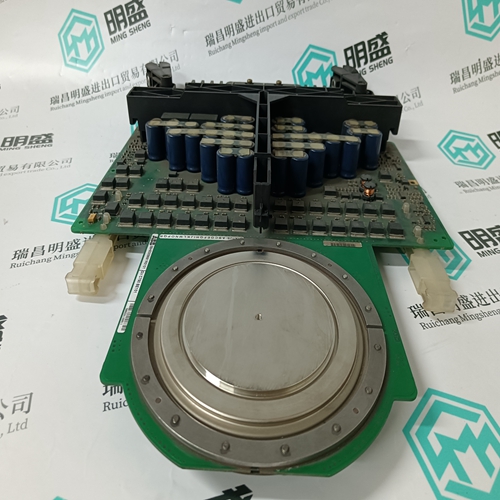
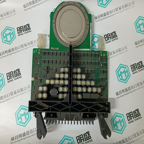
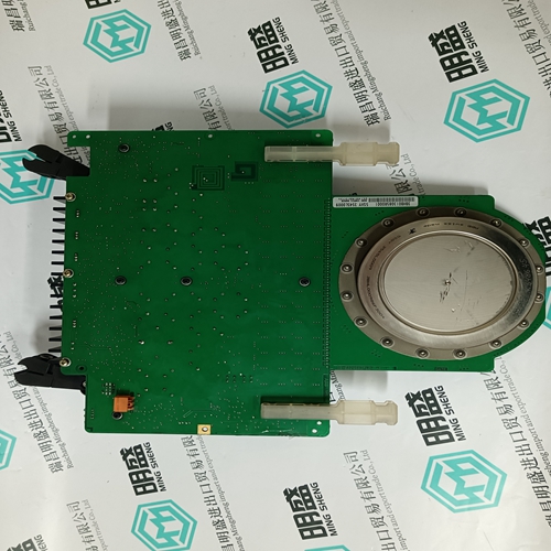
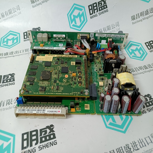
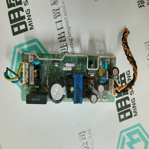
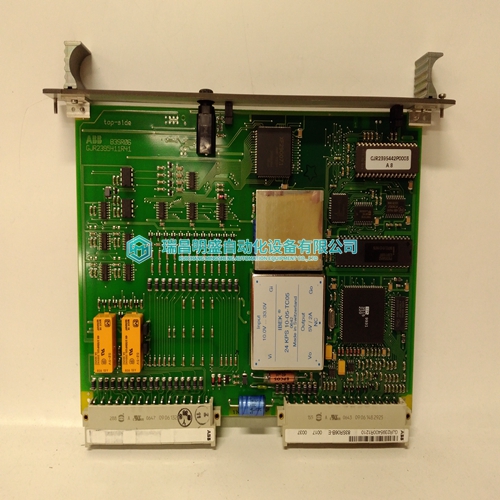
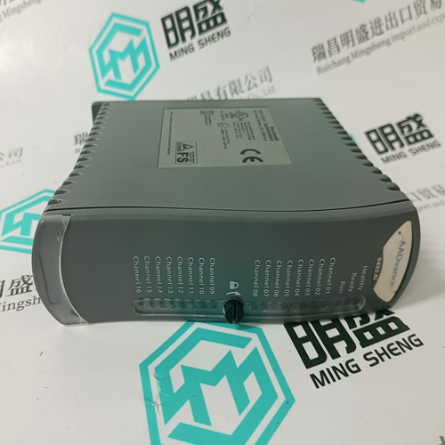
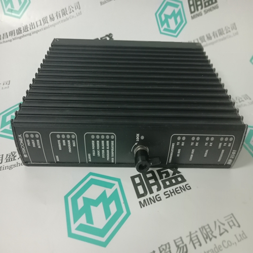
5SHY3545L0009 3BHB013085R0001 Thyristor module
- Product ID: 5SHY3545L0009 3BHB013085R0001
- Brand: ABB
- Place of origin: The Swiss
- Goods status: new/used
- Delivery date: stock
- The quality assurance period: 365 days
- Phone/WhatsApp/WeChat:+86 15270269218
- Email:stodcdcs@gmail.com
- Tags:5SHY3545L0009 3BHB013085R0001Thyristor module
- Get the latest price:Click to consult
The main products
Spare parts spare parts, the DCS control system of PLC system and the robot system spare parts,
Brand advantage: Allen Bradley, BentlyNevada, ABB, Emerson Ovation, Honeywell DCS, Rockwell ICS Triplex, FOXBORO, Schneider PLC, GE Fanuc, Motorola, HIMA, TRICONEX, Prosoft etc. Various kinds of imported industrial parts
5SHY3545L0009 3BHB013085R0001 Thyristor module
P249 bit functions The parameter includes the PWM/ analogue switchover, the idle state control of both air pressure switches LDW Low / LDW High and a ramp function (desired value delay). The output of the correct signal depends on the switch position (centre=voltage output signal), (bottom=PWM output signal), which must be identical to the setting of this parameter. The parameter is divided into 16 bits: Bit 0 Setting 0: PWM output. Set slide switch to PWM output (bottom position). Setting 1: Analogue output. Set slide switch to voltage (centre position) or current (top position). All parameter values in % are now converted to the output of the analogue value. Example: A post-venting parameter of 6000 gives 6 V at the analogue output, etc. Bit 1 Setting 0: Voltage output active 0..10 V Setting 1: Current output active 4..20 mA
The ramp (desired value delay) of the output signal is active during each change in speed. The More Heat / Less Heat inputs have priority if they are active. Bit 14 Reserved: Setting 0 Bit 15 Reserved: Setting 0
Profibus input data MPA to master
Input data is information about the state of the MPA. The input data contain a different number of bytes, depending on the data transfer module used. The lower bytes are always the same, i.e. Basic transfer is included in Standard transfer, Standard transfer in Extended transfer. Basic transfer 2 bytes EB0 and EB1 Standard transfer 7 bytes EB0 to EB6 Extended transfer 15 bytes EB0 to EB14 Special Extended transfer 25 bytes EB0 to EB24 The bytes EB0 and EB1 contain bit information. If the bit is set to 1, the condition is included in the description of the bits. Some bits are active during the fault (marked with "X"), others are 0
The quality of the flame signal is displayed for flame guard 1 as a number between 0 and 58. Evaluation of the flame signal is only possible with ionisation flame monitoring, also by monitoring with UV 41 (HE). When using the UV42, FLW 10 IR or FLW 20 UV, the maximum value is always displayed
