Home > Product > PLC programmable module > IC698CPE030-GJ The module
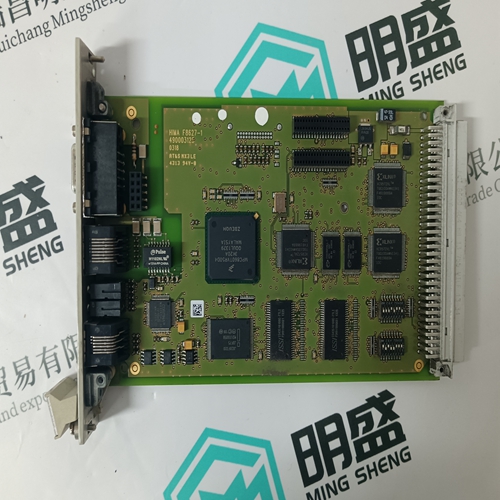
IC698CPE030-GJ The module
- Product ID: IC698CPE030-GJ
- Brand: GE
- Place of origin: the United States
- Goods status: new/used
- Delivery date: stock
- The quality assurance period: 365 days
- Phone/WhatsApp/WeChat:+86 15270269218
- Email:stodcdcs@gmail.com
- Tags:IC698CPE030-GJThe module
- Get the latest price:Click to consult
The main products
Spare parts spare parts, the DCS control system of PLC system and the robot system spare parts,
Brand advantage: Allen Bradley, BentlyNevada, ABB, Emerson Ovation, Honeywell DCS, Rockwell ICS Triplex, FOXBORO, Schneider PLC, GE Fanuc, Motorola, HIMA, TRICONEX, Prosoft etc. Various kinds of imported industrial parts
IC698CPE030-GJ The module
3. Loosen the Display Assembly’s two faceplate screws. One is above the numeric display and one behind the flip-down door at the bottom of the faceplate. 4. Pull the Assembly from the panel about 1.5" (38 mm). 5. Look behind the Assembly and locate the display cable from the MPU Controller board. Open the connector locking levers on the Assembly mounted connector to eject the cable mounted connector. 6. Place the Display Assembly in a static shielding bag and set it aside. 7. Go to the following sections to remove a circuit board or replace the power input fuse. INSTALLATION 1. Hold the Display Assembly close to the open case and mate the display cable with the connector on the Display Assembly circuit board. Check that the locking levers on the connector fully engaged the cable mounted connector. The cable is keyed. 2. Align the Display Assembly with the case. To ensure water tightness, use a torque screwdriver set to 6 inchpounds to tighten the two faceplate screws. Alternatively, use a screwdriver to tighten the screws until a slight resistance is felt, then tighten an additional ½ turn. DO NOT OVERTIGHTEN. 3. Remove the wrist strap. NOTE When changing a Display Assembly with the controller powered-up and an error code present, the displays will light in a random pattern except for the alphanumeric display which will show the error code. Clear the error to clear the displays.
11.5.2.2 To Replace the Bezel or Circuit Board
REMOVAL 1. Place a properly grounded wrist strap on your wrist and remove the Display Assembly as described above. 2. Refer to the figure below. Notice that the circuit board is captured by a Fixed Retainer at the top of the bezel and a Flexible Retainer at the bottom. Grasp the body of the black connector at “A” and at the same time press the Flexible Retainer downward slightly. Pull gently on the connector to lift the bottom edge of the board above the Flexible Retainer. Note The board is a snug fit. Do not squeeze the bezel sides and make removal more difficult. 3. Remove the board from the bezel by carefully continuing to lift board while pulling the board out from under to Fixed Retainer at the top of the assembly. 4. If the bezel is being replaced: 1) Remove the two Display Assembly mounting screws. Turn the Assembly face up and lift each mounting screw upward until the threaded portion contacts the bezel. Turn each screw counterclockwise to unscrew it from the bezel. A screwdriver may be needed once a screw is started. 2) Remove the flip-down door by pressing on the door near its pivot point to free the door from the bezel.