Home > Product > DCS control system > YOKOGAWA CP451-50 CPU module
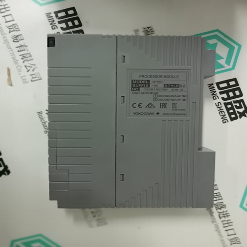
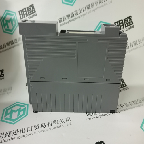
YOKOGAWA CP451-50 CPU module
- Product ID: CP451-50
- Brand: YOKOGAWA
- Place of origin: Japan
- Goods status: new/used
- Delivery date: stock
- The quality assurance period: 365 days
- Phone/WhatsApp/WeChat:+86 15270269218
- Email:stodcdcs@gmail.com
- Tags:YOKOGAWACP451-50CPU module
- Get the latest price:Click to consult
The main products
Spare parts spare parts, the DCS control system of PLC system and the robot system spare parts,
Brand advantage: Allen Bradley, BentlyNevada, ABB, Emerson Ovation, Honeywell DCS, Rockwell ICS Triplex, FOXBORO, Schneider PLC, GE Fanuc, Motorola, HIMA, TRICONEX, Prosoft etc. Various kinds of imported industrial parts
YOKOGAWA CP451-50 CPU module
Device version IRDH275B includes the following additional functions: • History memory with real-time clock to store all alarm messages with date and time stamp • Electrically isolated RS-485 interface (BMS protocol) for communication with other Bender devices • Isometer disconnecting relays for the operation of several ISOMETER®s in coupled IT systems • Current output 0(4 )…20 mA (electrically isolated)
Only one ISOMETER® may be active when several IT systems are coupled. Isometer disconnecting relays and the control inputs F1/F2 integrated in version IRDH275B guarantee that only one ISOMETER® is active at any one time. Measurement method The IRDH275(B) uses the patented AMPPlus measurement method. This measurement method allows concise monitoring of modern power supply systems, also in case of extensive, directly connected DC components and high system leakage capacitances
1 - “INFO” button: to query standard information ESC button: back to the menu function 2 - “TEST” button: to call up the self test Arrow up button: Parameter changes, scroll 3 - “RESET” button: to delete alarm and fault messages Arrow down button: Parameter change, scroll. 4 - “MENU” button: to activate the menu system Enter button: to confirm parameter changes 5 - Alarm LED “1” lights: insulation fault, 1st warning level reached 6 - Alarm LED “2” lights: insulation fault, 2nd warning level reached 7 - LED lights: system fault 8 - LC display
Wiring diagram
1 - Supply voltage US (see ordering information) via 6 A fuse; for UL and CSA applications, it is mandatory to use 5 A fuses. 2,3 - Connection to the 3AC system being monitored: Connect the terminals L1, L2 to neutral conductor N or terminals L1, L2 to conductor L1, L2. 4 - Connection to the AC system to be monitored: Connect terminals L1, L2 to conductor L1, L2. 5 - Connection of the DC systems being monitored: Connect terminal L1 to conductor L+, terminal L2 to conductor L6 - Separate connection of the equipotential bonding conductor to PE and KE *7 - External test button “T1/T2” (N/O contact) *8 - External reset button “R1/R2” (N/C contact or wire jumper) When the terminals are open, the fault message will not be stored, provided that the memory has not been activated via the operating menu. *9 - STANDBY by means of the function input “F1, F2”: with the contact in closed position no insulation measurement takes place (Isometer disconnection B version only/no disconnection when operated via AK). 10 - IRDH275: Currrent output, electrically isolated: 0…400 µA IRDH275B: Currrent output, electrically isolated: 0…20 mA or 4…20 mA 11 - RS-485 interface 12 - Alarm relay: Alarm 1 13 - Alarm relay: Alarm 2/system * The terminal pairs 7, 8 and 9 must be wired galvanically isolate and must not have a connection to PE!