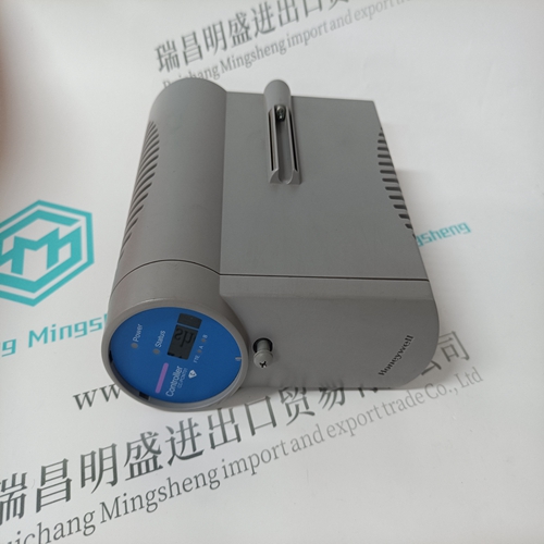
Home > Product > DCS control system > DSBC172 57310001-KD Control card
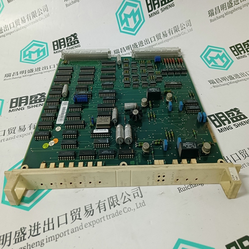
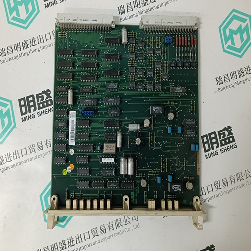
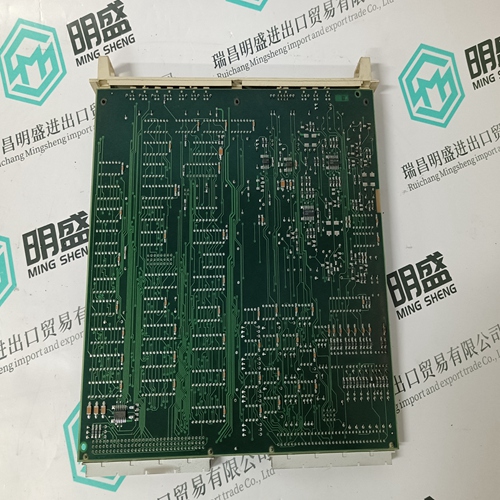
DSBC172 57310001-KD Control card
- Product ID: DSBC172 57310001-KD
- Brand: ABB
- Place of origin: The Swiss
- Goods status: new/used
- Delivery date: stock
- The quality assurance period: 365 days
- Phone/WhatsApp/WeChat:+86 15270269218
- Email:stodcdcs@gmail.com
- Tags:DSBC172 57310001-KDControl card
- Get the latest price:Click to consult
The main products
Spare parts spare parts, the DCS control system of PLC system and the robot system spare parts,
Brand advantage: Allen Bradley, BentlyNevada, ABB, Emerson Ovation, Honeywell DCS, Rockwell ICS Triplex, FOXBORO, Schneider PLC, GE Fanuc, Motorola, HIMA, TRICONEX, Prosoft etc. Various kinds of imported industrial parts
DSBC172 57310001-KD Control card
The drive enable logic is based on the following variable switches and flags: ACTIVE: This is the overall readiness flag indicating the enable/disable state of the drive. If high (1), the drive is enabled and power is being applied to motor. The following equation must hold true for ACTIVE to go high: ACTIVE = (READY) AND (REMOTE) where READY = (DRIVEOK) AND (SWEN) READY: Flag that indicates the drive is free of faults and ready to hardware enable. DRIVEOK: Switch indicates the status of the drive faults. SWEN: Switch indicates the status of the software enable (EN or DIS). REMOTE: Switch indicates the status of the hardware Remote Enable line on the C3 connector.If the drive will not enable, check the state of the switches and flags by clicking the “Status” button in the upper right-hand corner of the Main MOTIONLINK screen. If using a terminal, you can query the drive for the value stored in the STATUS variable. The Status Display indicates an enabled drive when the decimal point is illuminated solid.
The SERVOSTAR provides a motor position output to you in the form of quadrature encoder signals eliminating the need for an additional position feedback device. The outputs are differential line drivers. There is an associated DC common output (C4: pin 3) which can connect to your port to keep common mode noise and voltage spikes minimized for device protection. Because there are normally differences of potential between your controller and the drive, connection is recommended (if ground loops occur, disconnect and retest).
Incremental Encoder
The output signal is the actual encoder feedback signal that is pre-configured (MENCRES) in the drive’s motor parameters. It can be scaled down by multiples of two (ENCOUTO: 1, 2, 4, 8, 16) and has a maximum frequency limit of 3 MHz. The SERVOSTAR can use encoder feedback to monitor the motor shaft position. As opposed to a resolver, which is an absolute position feedback device, the encoder is an incremental device that indicates changes in position. The encoder resolution of the SERVOSTAR (and therefore the drive’s encoder equivalent output) is fixed because it is a hardware characteristic of the encoder device. The encoder interface includes three groups of wires: 1. A/B (and complements) lines make up the encoder quadrature signals. The signals are received differentially through line receivers before being passed through a wire-break detection circuit. 2. The narrow Index pulse normally appears once per revolution and indicates a known physical position of the shaft. This pulse is received differentially through a line receiver before being passed through a wire-break detection circuit. This signal is hardwarecapturable. 3. Hall signals provide information representing the approximate absolute location of the motor shaft. From this information, the motor can sinusoidally commutate forward until the index signal is detected - at which time, true position is known. These signals are isolated by an opto-coupler and can be differential or open-collector type signals.
