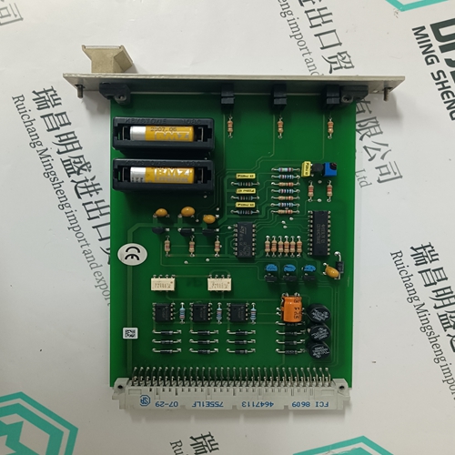
Home > Product > DCS control system > TRICONEX 2658 Communication module
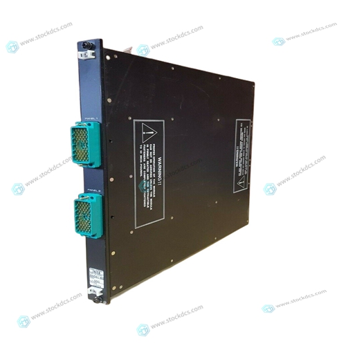
TRICONEX 2658 Communication module
- Product ID: 2658
- Brand: TRICONEX
- Place of origin: The United States
- Goods status: new/used
- Delivery date: stock
- The quality assurance period: 365 days
- Phone/WhatsApp/WeChat:+86 15270269218
- Email:stodcdcs@gmail.com
- Tags:TRICONEX2658Communication module
- Get the latest price:Click to consult
TRICONEX 2658 Communication module
The range of values which can be entered is 0 to 999, equivalent to inertia ratios up to 99.9:1. Please see Table 2-1 for motor moments of inertia. Do not include the motor inertia with the external load inertia in the calculations. Enter the calculated values of P81 and P82 as described in step 2. 5. Temporarily short-circuit X8/1 and X8/2, and energise the drive by setting P34 to 1. The motor shaft will start rotating slowly. 6. Adjust the signal balance by setting parameter P31 to 1, to activate the auto balance adjustment. A further fine adjustment can be made by altering the value of P30. 7. Position the 10Kohm potentiometer to mid track and remove the short circuit link between X8/1 and X8/2. The basic configuration can be assumed to be working if velocity control of the motor is achieved by the adjustment of the potentiometer. 8. After the drive is fully configured, set P0 to 270. This prevents further adjustment of any of the drive parameters - effectively locking out the front panel adjustment.
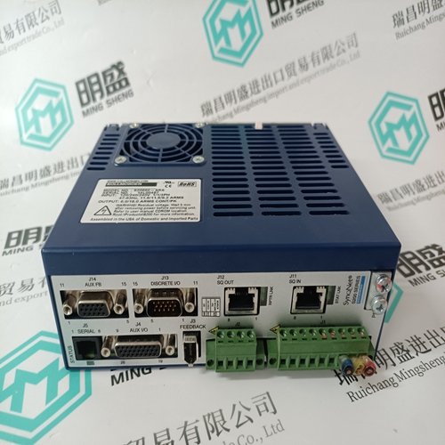
Installation of SV-S Drives
This section describes the installation of SV-S drives, and contains information that is specific to SV-S drives. Information common to all SV drives, such as programming and I/O interfacing is fully described in later sections. Generally, the differences between the multiaxis and stand-alone drive types is restricted to power connections, motor connections and certain mechanical mounting options.
The drive must be installed in an enclosure to protect
it from atmospheric contaminants such as oil, moisture, dirt, etc. No operator access should be allowed to the drive while it has AC power applied. Metal equipment cabinets offer the most advantages for siting the equipment since they can provide operator protection, EMC screening and can be fitted with interlocks arranged to remove all AC power when the cabinet door is open. Provision must also be made within the installation to contain the spread of fire by the fitting of a flame barrier, as defined in the LVD enclosure requirements. In many applications this requirement will be met simply by installing the drive within a cabinet fitted with a solid metal base. If the cabinet base is ventilated a flame barrier will be required that conforms with the baffle dimensions defined in the European Standard EN 61010-1.


Common problem
We have this product in stock, and we can deliver it to you at any time when you need it badly.
*The warranty period of all products is 1 year, which has passed the professional test certification.
*If you need to order more than one product, please contact us, and we can offer you a discount.
*We only use HDL UPS and other express delivery methods to deliver spare parts.
*If you find that other suppliers offer lower prices for the same products, we are also willing to offer you further discounts based on their prices.
If you have any other questions, please feel free to contact us via email.
*Please let us know if you need any spare parts, we can give you further assistance, and we are waiting for your inquiry.
