Home > Product > DCS control system > ABB HIEE300890R001 DC input module
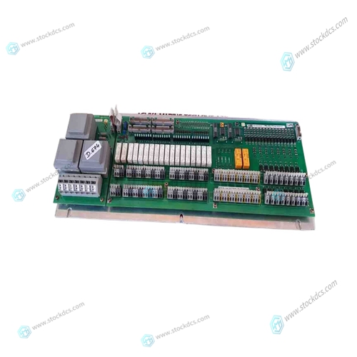
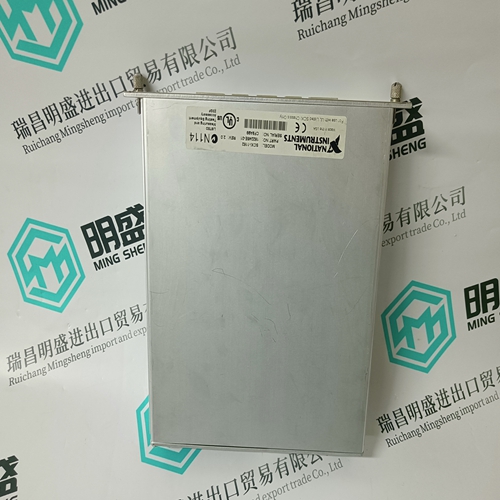
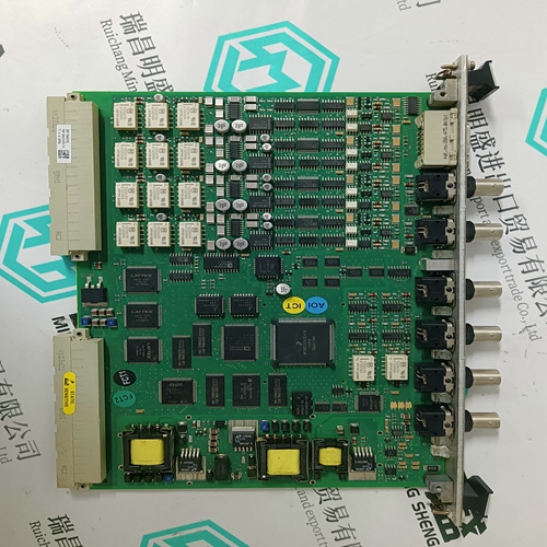
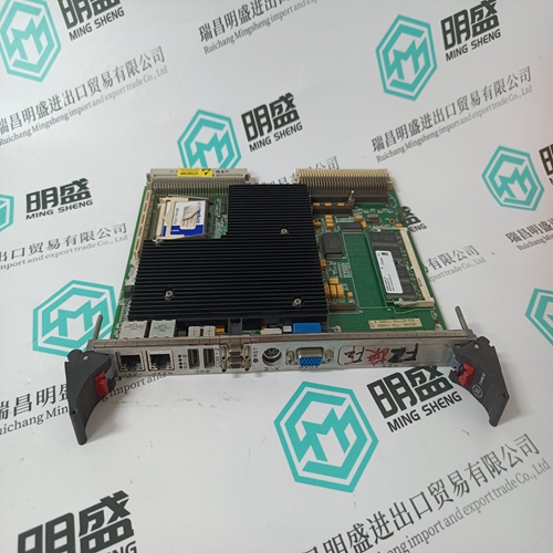
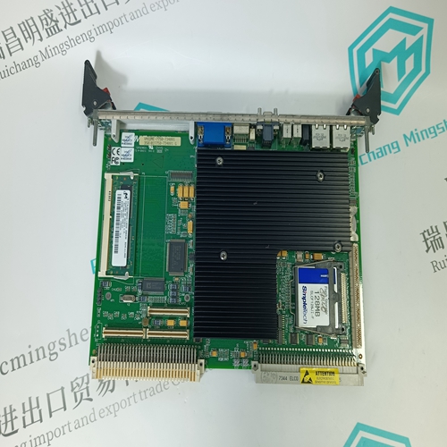
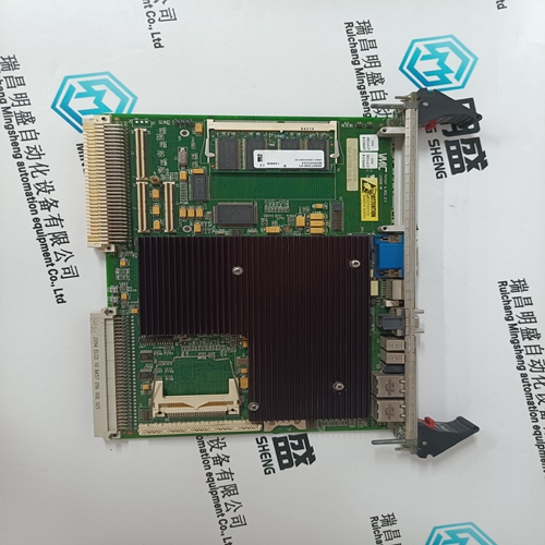
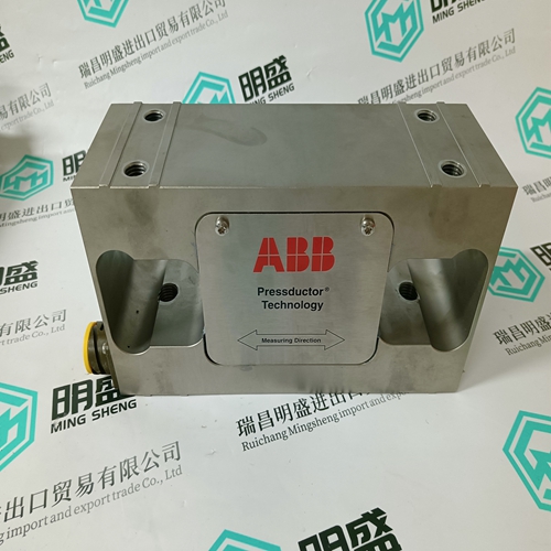
ABB HIEE300890R001 DC input module
- Product ID: HIEE300890R001
- Brand: ABB
- Place of origin: The Swiss
- Goods status: new/used
- Delivery date: stock
- The quality assurance period: 365 days
- Phone/WhatsApp/WeChat:+86 15270269218
- Email:stodcdcs@gmail.com
- Tags:ABBHIEE300890R001DC input module
- Get the latest price:Click to consult
ABB HIEE300890R001 DC input module
Motor and brake connections are located on the base of the drive for SV4500S and SV8500S drives, as shown in Figure 3-17. The resolver connector (X12 15-way female D-type) is also located on the base and will need to be connected to the motor using a resolver cable type REK 5 for the HDX115 motor or cable type REK 14 for the HDX142 motor.The pre-installation test circuits should use standard motor and resolver cables (see Appendix A), appropriate for the motor/drive combination being used. AC supply wiring should be made with insulated copper conductors with a cross sectional area of at least 2.5mm2 and a voltage rating of 1500V AC RMS (14 AWG tri-rated cable). Other stop, 24V and control wiring can use 16/0.2 mm (0.5 mm2) equipment wire. The protective earth conductor should be at least the same size as the supply wiring.
Testing the SV-S
1Power up the drive whilst holding down the ‘-’ button on the front panel. This ensures the motor will be de-energised. 2. Using the front panel buttons, press ‘+’ to enter the parameter mode setup (a ‘P’will be visible on the display), press ‘enter’ to select a particular parameter. Using the ‘+’ and ‘-’ buttons parameter numbers can be selected by ramping up and down the list of numbers available. Select parameter P0, press ‘enter’ to give it a value, and again using the ‘+’ and ‘-’ buttons ramp up to the value 302, then press ‘enter’. This procedure has assigned parameter P0 the value 302 which is a password that enables you to change drive parameters.
Enter the calculated values of P81 and P82 as described in step 2.
In this case, with no load attached to the motor, set P81=0 and P82=10. 5. Temporarily short-circuit X8/1 and X8/2, and energise the drive by setting P34 to 1. The motor shaft will start rotating slowly. 6. Adjust the signal balance by setting parameter P31 to 1, to activate the auto balance adjustment. A further fine adjustment can be made by altering the value of P30. 7. Position the 10Kohm potentiometer to mid track and remove the short circuit link between X8/1 and X8/2. The basic configuration can be assumed to be working if velocity control of the motor is achieved by the adjustment of the potentiometer. 8. After the drive is fully configured. Set P0 to 270. This prevents further adjustment of any of the drive parameters - effectively locking out the front panel adjustment.


Common problem
We have this product in stock, and we can deliver it to you at any time when you need it badly.
*The warranty period of all products is 1 year, which has passed the professional test certification.
*If you need to order more than one product, please contact us, and we can offer you a discount.
*We only use HDL UPS and other express delivery methods to deliver spare parts.
*If you find that other suppliers offer lower prices for the same products, we are also willing to offer you further discounts based on their prices.
If you have any other questions, please feel free to contact us via email.
*Please let us know if you need any spare parts, we can give you further assistance, and we are waiting for your inquiry.
