Home > Product > PLC programmable module > MOTOROLA MVME300 Voltage module
MOTOROLA MVME300 Voltage module
- Product ID: MVME300
- Brand: MOTOROLA
- Place of origin: The United States
- Goods status: new/used
- Delivery date: stock
- The quality assurance period: 365 days
- Phone/WhatsApp/WeChat:+86 15270269218
- Email:stodcdcs@gmail.com
- Tags:MOTOROLAMVME300Voltage module
- Get the latest price:Click to consult
MOTOROLA MVME300 Voltage module
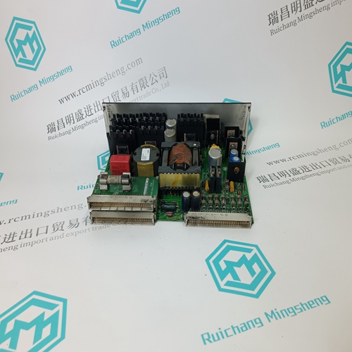
Module Power Check model/serial number label for module operating voltage to make sure it matches available power. When using DC power, either polarity is acceptable, but for consistency with similar API products, positive (+) can be wired to terminal 13 and negative (–) can be wired to terminal 16. Installation Location The housing clips to a standard 35 mm DIN rail. The housing is IP40 rated and should be mounted inside a panel or enclosure. Mounting to a DIN Rail Install module vertically on a 35 mm DIN rail in a protective enclosure away from heat sources. Do not block air flow. Allow 1" (25 mm) above and below housing vents for air circulation. 1. Tilt front of module downward and position against DIN rail. 2. Clip lower mount to bottom edge of DIN rail. 3. Push front of module upward until upper mount snaps into place.
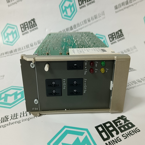
Calibration Input and output ranges
if specified on your order, are factory pre-configured (at 24°C ±1°C). Front-mounted Zero and Span potentiometers are used to calibrate the output to compensate for load and lead variations. Note: Perform the following calibration procedure any time switch settings are changed. 1. Apply power to the module and allow a minimum 20 minute warm up time. 2. Using an accurate calibration source, provide an input to the module equal to the minimum input required for the application. 3. Using an accurate measurement device for the output, adjust the Zero potentiometer for the exact minimum output desired. The Zero control should only be adjusted when the input signal is at its minimum. This will produce the corresponding minimum output signal. For example: 4 mA for a 4-20 mA output or –10 V for a ±10V output
Set the input at maximum
adjust the Span pot for the exact maximum output desired. The Span control should only be adjusted when the input signal is at its maximum. This will produce the corresponding maximum output signal. Example: for 4-20 mA output, the Span control will provide adjustment for the 20 mA or high end of the signal. 5. Repeat adjustments for maximum accuracy. Output Test Function When the Test button is depressed it will drive the output with a known good signal that can be used as a diagnostic aid during initial start-up or troubleshooting. When released, the output will return to normal. The Test Cal. potentiometer is factory set to approximately 50% output. It can be adjusted to set the test output from 0 to 100% of the output span. Press and hold the Test button and adjust the Test Cal. potentiometer for the desired output level.

Quality assurance service
1. We provide high-quality parts of various brands, and you will find full
The model meets your needs.
2. For models that have been out of production for many years, we have all hard to find parts, so we can directly find us to solve all problems for you at one time.
3. If you are in a hurry to use this product, we can dispatch it for you.
4. All products can enjoy a one-year warranty service,
5. Our products are new and unused.
6. If you need a large quantity, you can contact us and I can offer you a discount.
7. You can ask me about the price and more information about the product via email. We welcome you