Home > Product > Robot control system > MOLEX DR2-DPM-PCU Axial displacement card
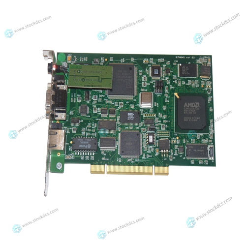
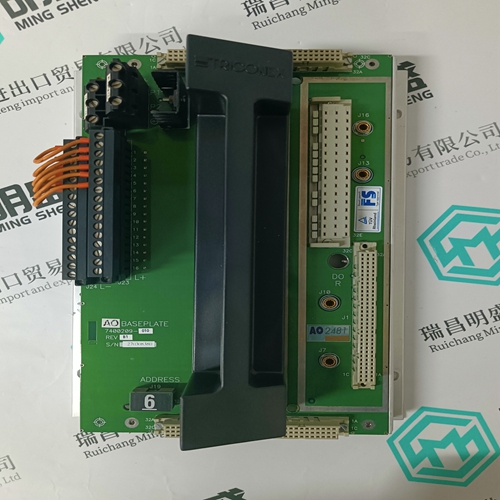
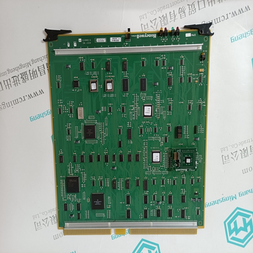
MOLEX DR2-DPM-PCU Axial displacement card
- Product ID: DR2-DPM-PCU
- Brand: MOLEX
- Place of origin: The United States
- Goods status: new/used
- Delivery date: stock
- The quality assurance period: 365 days
- Phone/WhatsApp/WeChat:+86 15270269218
- Email:stodcdcs@gmail.com
- Tags:MOLEXDR2-DPM-PCUAxial displacement card
- Get the latest price:Click to consult
MOLEX DR2-DPM-PCU Axial displacement card
The Load Sharing Module is in the droop mode when EITHER the droop contact or the circuit breaker auxiliary contact is open. If the droop contact is open, the Load Sharing Module remains in the droop mode even when the circuit breaker auxiliary contact is closed. If droop is not desired when the auxiliary contact is open, turn the droop potentiometer fully counterclockwise. Use a single pole, single-throw switch with a 0.1 A minimum rating for the “open for droop” switch.Use twisted 0.5 mm² (20 AWG) or larger shielded wire to connect the output signal from terminals 19, 20, and 21 to the engine speed control. Connect the shield to the closest chassis screw only. Do not connect the shield at the speed control end of the wiring
Synchronization Connections
If an SPM-A synchronizer is used, connect twisted-pair 0.5 mm² (20 AWG) or larger shielded wire from the synchronizer to terminals 24(+) and 25(–). Tie the shield to the closest chassis screw. Do not connect the shield at the synchronizer end of the wiring.Use this calibration procedure after a Load Sharing Module is installed on a generator set, to obtain the needed operating characteristics during load sharing. 1. Check that the correct jumpers are installed on terminals 15, 16, 17, and 18 to match your potential transformer secondary voltage. See the plant wiring diagram Remove wires from load sharing line terminals 10 and 11, and from the SPM-A Synchronizer (if used) at terminals 24 and 25.
Phase Correction Procedure
If this procedure is followed, the correct connection of the current transformers is assured; the correct CT will be connected to the correct input on the Load Sharing Module with the correct polarity. Use this procedure only if the Phasing Check indicates that the phasing is incorrect. A CT for any phase (A, B, or C), will produce the most positive load signal voltage when it is connected, in the proper polarity, to the terminals on the Load Sharing Module which correspond to the same phase. Any other connections of this CT will produce a less positive load signal voltage. This procedure makes trial connections of the first CT to all three CT inputs on the Load Sharing Module, polarized both ways on each CT input. The load signal voltage is recorded for each connection, and the CT is then connected to the CT input terminals that produced the most positive load signal voltage and with the polarity that produced the most positive load signal voltage


Quality assurance service
1. We provide high-quality parts of various brands, and you will find full
The model meets your needs.
2. For models that have been out of production for many years, we have all hard to find parts, so we can directly find us to solve all problems for you at one time.
3. If you are in a hurry to use this product, we can dispatch it for you.
4. All products can enjoy a one-year warranty service,
5. Our products are new and unused.
6. If you need a large quantity, you can contact us and I can offer you a discount.
7. You can ask me about the price and more information about the product via email. We welcome you
