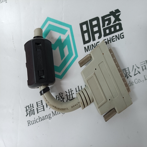
Home > Product > DCS control system > TRICONEX PI3381 Industrial control card a
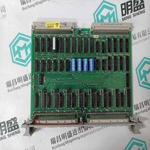
TRICONEX PI3381 Industrial control card a
- Product ID: PI3381
- Brand: TRICONEX
- Place of origin: The United States
- Goods status: new/used
- Delivery date: stock
- The quality assurance period: 365 days
- Phone/WhatsApp/WeChat:+86 15270269218
- Email:stodcdcs@gmail.com
- Tags:TRICONEX PI3381Industrial control card a
- Get the latest price:Click to consult
The main products
Spare parts spare parts, the DCS control system of PLC system and the robot system spare parts,
Brand advantage: Allen Bradley, BentlyNevada, ABB, Emerson Ovation, Honeywell DCS, Rockwell ICS Triplex, FOXBORO, Schneider PLC, GE Fanuc, Motorola, HIMA, TRICONEX, Prosoft etc. Various kinds of imported industrial parts
TRICONEX PI3381 Industrial control card a
Orient the connector on this end of the cable as shown above to mate with the RJ-45 connector inside the case, on the connector socket assembly. Guide the cable into the case and insert the cable-mounted connector into the case-mounted connector.It may be necessary to gently press on the clear plastic connector with a long straight-blade screwdriver to seat the cable-mounted connector.Ethernet Board Connection: Install the MPU Controller board with the attached Ethernet board in the controller case. Locate the RJ-45 connector (J4) on the exposed edge of the Ethernet board. Note the connector orientation. Orient the cable-mounted connector to mate with the board-mounted connector and insert the cablemounted connector.
Note AINU1-2, Analog Input Universal, refer to the AINU description in Section 3 Function Blocks for calibration information. When field calibrating a controller for a critical application, consider the following: • If the input is a current signal (e.g., 4-20 mA), use a precision current source. The 250 ohm precision range resistor installed across the input terminals for calibration should remain with the station, connected across that set of terminals, to eliminate the voltage drop variation due to resistor tolerance. • Allow the Station to warm-up for an hour prior to calibration. The ambient temperature should be close to normal operating conditions.
12.0 CALIBRATION
A controller is factory calibrated to either the standard values listed in Section 8.5 or to values specified by the purchaser at time of order. Field calibration should not be necessary. For those cases where inputs or outputs must be adjusted either to meet a local standard or for a more critical application, a field calibration can be performed. The field calibration becomes the default calibration. A CAL VIEW mode is available in calibration to view the sensor input over the full range. The signal that is viewed, in the calibration verify mode, is 0 to 100% of span in basic units of measure (e.g., °C for temperature, mv for millivolts) and is not affected by the temperature units conversion, digital filter, scaling, or the output bias adjustment. The full block output in engineering units with these parameters applied can be seen in the VIEW mode within loop configuration. This section describes calibration and calibration verification of the following function blocks: AIN1-4 - Analog Input MPU board (3) and I/O Expander board (1) AOUT1-3 - Analog Output MPU board (2) and I/O Expander board (1)
