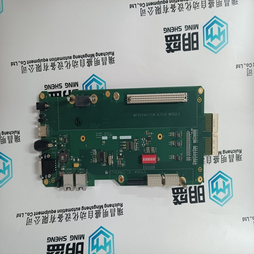
Home > Product > DCS control system > PFSK164 3BSE021180R1 Pulse control card
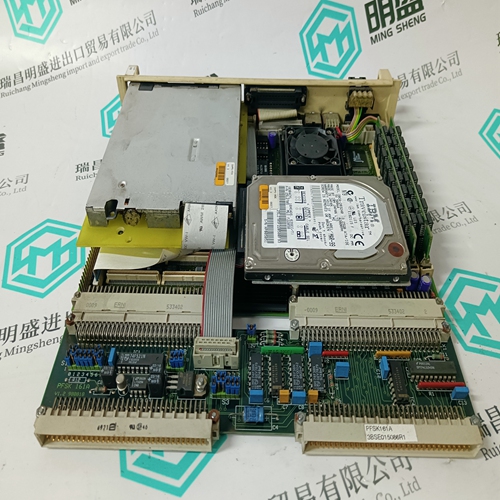
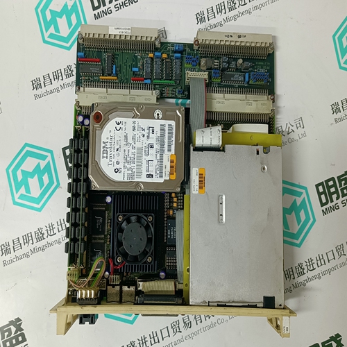
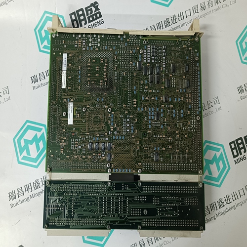
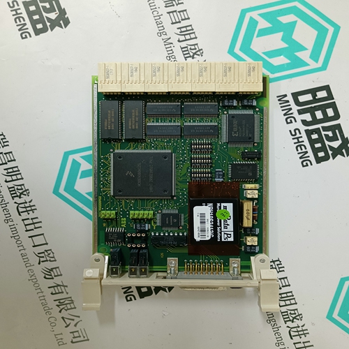
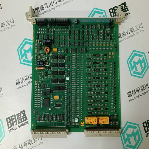
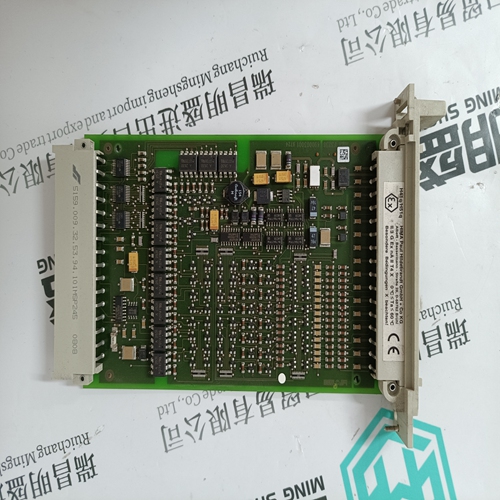
PFSK164 3BSE021180R1 Pulse control card
- Product ID: PFSK164 3BSE021180R1
- Brand: ABB
- Place of origin: The Swiss
- Goods status: new/used
- Delivery date: stock
- The quality assurance period: 365 days
- Phone/WhatsApp/WeChat:+86 15270269218
- Email:stodcdcs@gmail.com
- Tags:PFSK164 3BSE021180R1Pulse control card
- Get the latest price:Click to consult
The main products
Spare parts spare parts, the DCS control system of PLC system and the robot system spare parts,
Brand advantage: Allen Bradley, BentlyNevada, ABB, Emerson Ovation, Honeywell DCS, Rockwell ICS Triplex, FOXBORO, Schneider PLC, GE Fanuc, Motorola, HIMA, TRICONEX, Prosoft etc. Various kinds of imported industrial parts
PFSK164 3BSE021180R1 Pulse control card
A macro is selected in the Macro Select (2.01) parameter. After selection a function is assigned to each of the digital inputs DI1…DI8. The functions are described in the chapter Application Macros
Then the allocations will be dependent on the selected macro, see chapter Application Macros. The user can change the allocations manually any time. Then they are no longer “Macro Depend”. Hence the macro technique also allows the flexible, user-friendly adaptation to special requirements. analog outputs, which reference value sources are used, etc. is already defined in the macro. A macro is selected in the Macro Select (2.01) parameter. After selection a function is assigned to each of the digital inputs DI1…DI8. The functions are described in the chapter Application Macros. The following “selectors” (parameters) are predefined when you are selecting the macro provided that these parameters have their default settings or are set to Macro Depend: In addition to analog and digital outputs some of the digital inputs are re-configurable. The digital inputs DI1…DI4 in macros 1+5+6+7+8 can be set individually via parameter group 9 - MacroAdaptation. Macros 2+3+4 are fixed, not re-configurable. Example of MacroAdaptation: macro 6 - MotorPot should be selected digital input DI1 should be re-defined from "direction of rotation" to "alternativ parameter set" for using ramp 1 / 2 • Set parameter „Dir of Rotation" (9.09) from Macro depend to Disable • Set parameter „AlternativParam" (9.14) from Macro depend to DI1 • Set standard parameter set (5.07…5.10) and alternative parameter set (5.22…5.25) to values as required
Digital and analogue Inputs/Outputs
Digital inputs DI1…DI8 The drive is controlled via the digital inputs DI1…DI8. The significance of the inputs are defined by a macro. When you select a macro in the Macro Select (2.01) parameter the functions are assigned to the 8 digital inputs. The functions are described in the context of respective macros in section 4.2 Application Macros. The functions of the digital inputs DI1...DI4 of macros 1, 5, 6, 7 and 8 are re-configurable via parameter group 9. Digital outputs DO1…DO5 Any signal of a signal list can be assigned to each digital output. The list is available in the parameters of the digital outputs DO1…DO5 (DO1 Assign (6.11)…DO5 Assign (6.15)). The significance and/or mode of operation of the signals is described there. The outputs are connected with the application macro by default i.e. changing the macro will change the significance of the outputs. The linking of the macro will be revoked if you allocate another signal. Then the output will keep its significance even if the setting of the macro changes. Analog inputs AI1…AI2 (11 Bits + sign) The analog inputs are 10V inputs. Offset voltages for 0% and 100% reference can be entered into the scaling parameters 6.01…6.04: e.g.: A reference value is preset by means of a potentiometer. The zero position of the potentiometer is not exactly 0V but 0.8V and the full-scale deflection is not exactly 10V but 9.3 V. Enter 9.30 V into parameter AIx Scale 100 % (6.01 / 6.03) and 0.80V into parameter AIx Scale 0 % (6.02 / 6.04). The range between 0.80V and 9.30V is then considered to be the 100% reference value.
