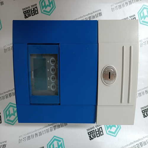
Home > Product > DCS control system > LXN1604-6 3BHL000986P7000 DIN rail power supply
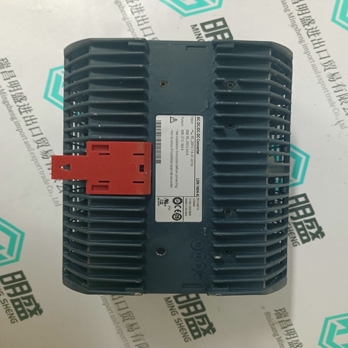
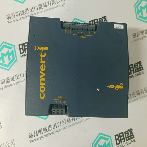
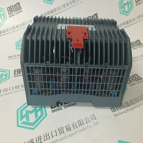
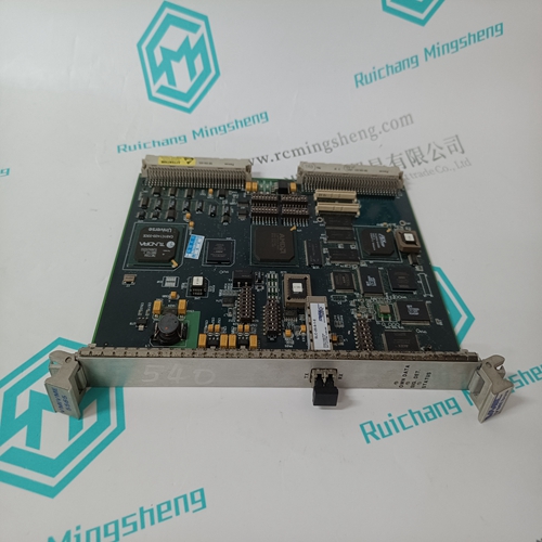
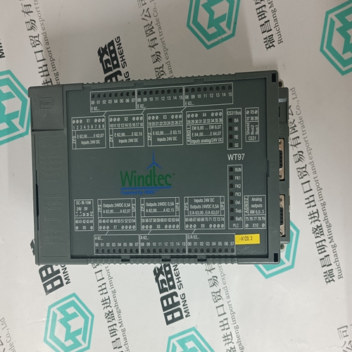
LXN1604-6 3BHL000986P7000 DIN rail power supply
- Product ID: LXN1604-6 3BHL000986P7000
- Brand: ABB
- Place of origin: The Swiss
- Goods status: new/used
- Delivery date: stock
- The quality assurance period: 365 days
- Phone/WhatsApp/WeChat:+86 15270269218
- Email:stodcdcs@gmail.com
- Tags:LXN1604-6 3BHL000986P7000DIN rail power supply
- Get the latest price:Click to consult
The main products
Spare parts spare parts, the DCS control system of PLC system and the robot system spare parts,
Brand advantage: Allen Bradley, BentlyNevada, ABB, Emerson Ovation, Honeywell DCS, Rockwell ICS Triplex, FOXBORO, Schneider PLC, GE Fanuc, Motorola, HIMA, TRICONEX, Prosoft etc. Various kinds of imported industrial parts
LXN1604-6 3BHL000986P7000 DIN rail power supply
Analog outputs AO1…AO2 (11 Bits + sign) Any actual value of an actual value list can be assigned to the analog outputs. The list is available in the AOx Assign parameters (6.05 / 6.08). The outputs are connected with the application macro by default i.e. changing the macro will change the significance of the outputs. The linking of the macro will be revoked if you allocate another actual value. Then the output will keep its new significance even if the setting of the macro changes. Using the parameter AOx Mode (6.06 / 6.09) you can choose between unipolar (0…10V) or bipolar (-10V…0V…+10V) output. The parameters AOx Scale 100 % (6.07 / 6.10) define which voltage level corresponds to 100% actual value. E.g.: A 200% armature current is required in a drive. These 200% can be represented maximally by 10V. According to a simple formula: (10V / 200%) x 100% AOx Scale shall be set to 5.00V (=100% armature current).
The speed feedback with tachogenerator is set with the parameter Speed Meas mode (5.02) = Tacho. The tachogenerator shall be connected to the appropriate inputs of the terminal block corresponding to its voltage level. The maximum tachogenerator voltage at maximum speed is decisive, e.g.: Tachogenerator selection: 60 V / 1000 rpm max. motor speed: 3000 rpm max. tachogenerator voltage: 180V
DCS400 accuracy
Analog values will be converted to digital values via Anlog Digital Converter (ADC). The accuracy of resolution depends on how much bits are used and is related to 100%. Bipolar values are marked at most significant bit (sign bit).
Some applications may require that the voltage potential of the tachogenerator be connected to the 0V potential of the converter and/or not be connected. This setting is made with the jumper S1:1-2. S1:1-2 jumpered: 0V connection between tachogenerator and converter S1:1-2 open: no 0V connection If a tachogenerator feedback is used the speed will require adjustment by means of potentiometer R115. The control panel or the PC tool support the adjustment during the prompted start-up. Encoder inputs ChA+…ChZSpeed feedback with a encoder is set in the parameter Speed Meas Mode (5.02) = Encoder and the encoder increments per revolution are set with the parameter Encoder Inc (5.03). The supply voltage for the encoder can be taken from the converter by setting the jumper appropriately. Jumper setting S2: 10-11 +5V encoder supply S2: 11-12 +24V encoder supply Connecting the signal lines can be unsymmetrical (without inverted signals) to the terminals X3:1 and X3:3 or symmetrical (with inverted signals) to X3:1...X3:4. The Z signal (including the inverted signal) is not needed in the DCS400.
