Home > Product > DCS control system > ABB YPG 111A 3ASD273001B1 POWER MEASURING UNIT
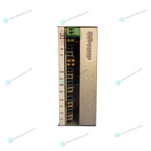
ABB YPG 111A 3ASD273001B1 POWER MEASURING UNIT
- Product ID: YPG 111A 3ASD273001B1
- Brand: ABB
- Place of origin: The Swiss
- Goods status: new/used
- Delivery date: stock
- The quality assurance period: 365 days
- Phone/WhatsApp/WeChat:+86 15270269218
- Email:stodcdcs@gmail.com
- Tags:ABBYPG 111A3ASD273001B1POWER MEASURING UNIT
- Get the latest price:Click to consult
ABB YPG 111A 3ASD273001B1 POWER MEASURING UNIT
The Timer2 counter performs 8-bit up-counting operation only; the counter values can be set or read back by tm2ct register. The 8-bit counter will be clear to zero automatically when its values reach for upper bound register, the upper bound register is used to define the period of timer or duty of PWM. There are two operating modes for Timer2: period mode and PWM mode; period mode is used to generate periodical output waveform or interrupt event; PWM mode is used to generate PWM output waveform with optional 6- bit or 8-bit PWM resolution, Fig. 12 shows the timing diagram of Timer2 for both period mode and PWM mode.
WatchDog Timer
The watchdog timer (WDT) is a counter with clock coming from ILRC and there are four different timeout periods of watchdog timer can be chosen by setting the misc register, it is: 256 ILRC clocks period if register misc[1:0]=11 2048 ILRC clocks period if register misc[1:0]=00 (default) 4096 ILRC clocks period if register misc[1:0]=01 16384 ILRC clocks period if register misc[1:0]=10 The frequency of ILRC may drift a lot due to the variation of manufacture, supply voltage and temperature; user should reserve guard band for save operation. WDT can be cleared by power-on-reset or by command wdreset at any time. When WDT is timeout, PMC234/PMS234 will be reset to restart the program execution. The relative timing diagram of watchdog timer is shown as Fig. 13.
Interrupt
There are six interrupt lines for PMC234/PMS234:
External interrupt PA0
External interrupt PB0
ADC interrupt
Timer16 interrupt
Timer2 interrupt
Comparator interrupt,


Application industry
The products can be used in the following industries: power plant, paper making, steel, mining, rubber, water supply, cement, chemical industry, glass, printing
Textile, machinery, plastics, coatings, medicine, hospitals, food, hotels, scientific research institutions
This article from the temporal Ming sheng automation equipment co., LTD., reproduced please attach this link: http://www.stockdcs.com/
