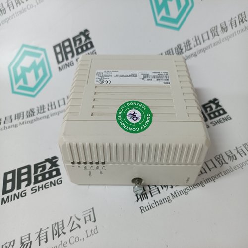
Home > Product > PLC programmable module > MOTOROLA MVME147-023 Logic sequence module
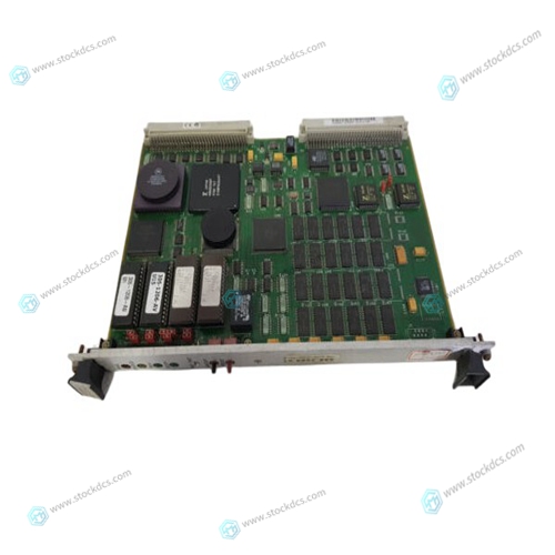
MOTOROLA MVME147-023 Logic sequence module
- Product ID: MVME147-023
- Brand: MOTOROLA
- Place of origin: The United States
- Goods status: new/used
- Delivery date: stock
- The quality assurance period: 365 days
- Phone/WhatsApp/WeChat:+86 15270269218
- Email:xiamen2018@foxmail.com
- Tags:MOTOROLAMVME147-023Logic sequence module
- Get the latest price:Click to consult
MOTOROLA MVME147-023 Logic sequence module
The comparator output is undetermined for a period of time after changing an input source or a new reference voltage; this period is referred as the response time. Please refer to Fig. 4-31 and Fig. 4-32 the measurement of comparator responsive time. Typically, the measurement will be based on the compared voltage level near (VDD-1.5)/2. If the compared voltage level is not within the range, the responsive time may be longer.
Using the comparator and band-gap 1.20V
The internal band-gap module can provide 1.20 volt, it can measure the external supply voltage level. The band-gap 1.20 volt is selected as minus input of comparator and Vinternal R is selected as plus input, the supply voltage of Vinternal R is VDD, the VDD voltage level can be detected by adjusting the voltage level of Vinternal R to compare with band-gap. If N (gpcs[3:0] in decimal) is the number to let Vinternal R closest to band-gap 1.20 volt, the supply voltage VDD can be calculated by using the following equations: For using Case 1: VDD = [ 32 / (N+9) ] * 1.20 volt ;
LCD Bias Voltage Generator
This function can be enabled by bit 4 of misc register. Those pins which are defined to output VDD/2 voltage are PA3、PA2、PA1、PA0 during input mode, being used as COM function for LCD application. If user wants to output VDD、VDD/2、GND three levels voltage, the corresponding pins must be set to output-high for VDD, enabling VDD/2 bias voltage with input mode for VDD/2, and output-low for GND correspondingly, Fig. 25 shows how to use this function.


Application industry
The products can be used in the following industries: power plant, paper making, steel, mining, rubber, water supply, cement, chemical industry, glass, printing
Textile, machinery, plastics, coatings, medicine, hospitals, food, hotels, scientific research institutions
This article from the temporal Ming sheng automation equipment co., LTD., reproduced please attach this link: http://www.stockdcs.com/
