Home > Product > Servo control system > B&R 7DO138.70 analog output module
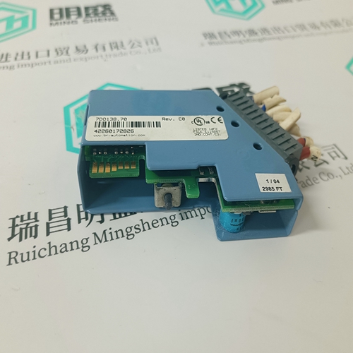
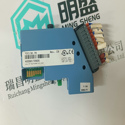
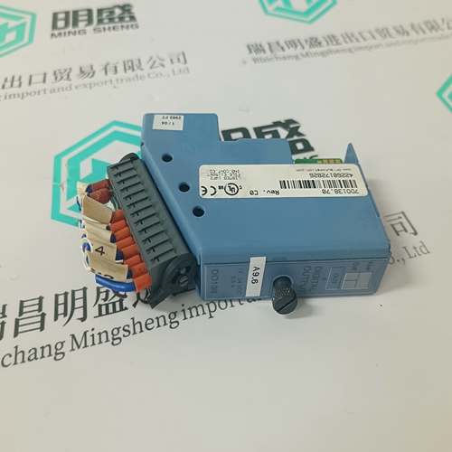
B&R 7DO138.70 analog output module
- Product ID: 7DO138.70
- Brand: B&R
- Place of origin: the United States
- Goods status: new/used
- Delivery date: stock
- The quality assurance period: 365 days
- Phone/WhatsApp/WeChat:+86 15270269218
- Email:stodcdcs@gmail.com
- Tags:B&R7DO138.70analog output module
- Get the latest price:Click to consult
The main products
Spare parts spare parts, the DCS control system of PLC system and the robot system spare parts,
Brand advantage: Allen Bradley, BentlyNevada, ABB, Emerson Ovation, Honeywell DCS, Rockwell ICS Triplex, FOXBORO, Schneider PLC, GE Fanuc, Motorola, HIMA, TRICONEX, Prosoft etc. Various kinds of imported industrial parts
B&R 7DO138.70 analog output module
Correlation of Armature Voltage and EMF The DCS 400 drive calculates the true EMF and does not take the Armature Voltage instead. EMF is calculated by EMFNOM = Arm VoltNOM - (Arm CurNOM x Arm Resistance) The Armature Resistance is measured during armature autotuning or can be entered manually. This means, without load and thus without current you will never get to full rated Armature Voltage but always full speed.
Because of the EMF based controller the drive uses Automatic Field Weakening as soon as the nominal EMF is reached to achieve full speed. But that’s only possible in tacho or encoder controlled mode, in EMF feedback there is no field weakening.
In the case of manual parameterization and no field weakening set both parameters to identical values. With field weakening: set the Base Speed to the nominal speed at nominal armature voltage and Max Speed to the maximum speed at maximum field weakening. If you parameterize the converter with the prompted start-up procedure (Panel Wizard) the parameters will be interrogated during entry and will be set appropriately. Field weakening is possible only with a tacho-generator or encoder feedback. If the EMF feedback is used the motor can be run only up to the nominal speed Base Speed (1.05). Higher reference values will not cause any increase in speed, there will be no field weakening.
With speed-dependent current limiting
Beyond the normal field weakening range, the armature current of a motor must be reduced because of the commutation problems to be expected. This speed is the maximum electrical speed of a motor. Set the parameter Cur Lim Speed (1.12) to the speed, from which the limitation shall be effective, for this speed dependent current limiting. Within the speed range between Cur Lim Speed (1.12) and Max Speed (1.06) the permissible armature current Cur Arm Max (3.04) is reduced to IaLim as a function of speed according to the following formula:Converter: DCS400 is equipped with an overtemperature protection on the heat sinks of the thyristors. When the maximum bridge temperature is reached DCS400 switches off with the fault message Converter Overtemp (F7). The converter can be switched on again only after sufficient cooling and acknowledgement of the fault. 5 °C below the cut-out temperature the warning Converter High Temp (A4) is output but the drive is not switched off. In case of overheating the Fan On signal will be active (fan coasting) until the converter has cooled down. The signal can be evaluated by means of the digital outputs DO1…DO5.
The temperature protection of the motor can be evaluated via a PTC element (usually in the field or commutating winding of the motor) in the DCS400. For this purpose the PTC element shall be connected to the AI2 analog input. The response of the DCS400 when the temperature monitor trips is set with the parameter PTC Mode (2.12). The tripping of the temperature monitor of the motor has the same effect on the Fan ON signal as the converter temperature monitor: The signal remains present until the motor temperature has decreased sufficiently
