Home > Product > Robot control system > VIBRO 200-582-915-032 VM600 Programmable card
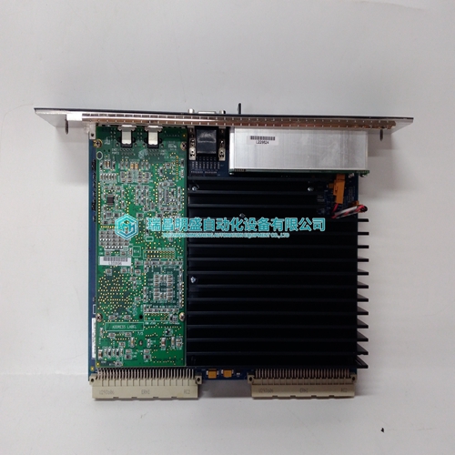
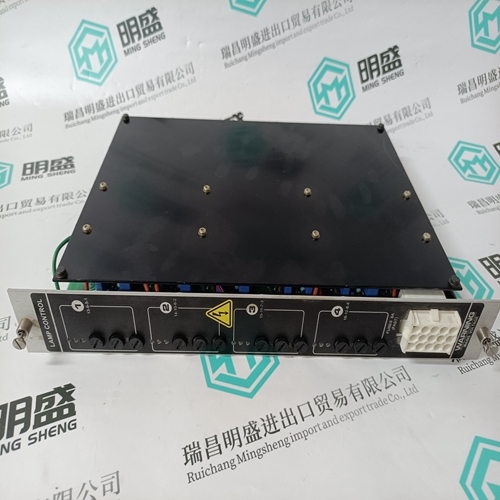
VIBRO 200-582-915-032 VM600 Programmable card
- Product ID: 200-582-915-032 VM600
- Brand: VIBRO
- Place of origin: the United States
- Goods status: new/used
- Delivery date: stock
- The quality assurance period: 365 days
- Phone/WhatsApp/WeChat:+86 15270269218
- Email:stodcdcs@gmail.com
- Tags:VIBRO200-582-915-032 VM600Programmable card
- Get the latest price:Click to consult
The main products
Spare parts spare parts, the DCS control system of PLC system and the robot system spare parts,
Brand advantage: Allen Bradley, BentlyNevada, ABB, Emerson Ovation, Honeywell DCS, Rockwell ICS Triplex, FOXBORO, Schneider PLC, GE Fanuc, Motorola, HIMA, TRICONEX, Prosoft etc. Various kinds of imported industrial parts
VIBRO 200-582-915-032 VM600 Programmable card
Voltage regulator operational test: Use the following test procedure to determine if the regulator is basically operational: 1. Connect regulator as shown in Figure 12. 2. Connect internal wire from terminal E3 to the tap on the sensing transformer T1 that matches the input power described in step 6. 3. Connect jumper across terminals CT and CT1. 4. Adjust the external voltage adjust for maximum resistance (complete counterclockwise position). If the light is on when voltage adjust is turned to its complete counterclockwise position, the problem is likely in the regulator. 5. Connect light bulb across terminals F+ and F- and wires to terminals E1, E3, P1, and P2 as shown in Figure 12. 6. Connect to 120 Vac power source when regulator full load output rating is 65 Vdc. Connect to 240 Vac power source when regulator full load output rating is 125 Vdc. 7. Turn the external voltage adjust clockwise. Before reaching the maximum clockwise position, the bulb should come on to near full brilliance. 8. At the regulating point a small change in adjustment of the external voltage adjust rheostat should turn the light on or off. If the light does not come on, the problem is likely in the regulator. 9. Before installing back in the generating system, connect the regulator as it was before steps 2 through 7. Troubleshooting: Between regular preventive maintenance inspections, be alert for any signs of trouble. Correct any trouble immediately. See Table 4 for typical symptoms, causes, and remedies.
INSTALLATION
1. With the arrow stamped onto the cap facing upwards, push the 16-pin connector from the AX-DSPX-WRharness into the left side of the cap. The locking clip on the connector should face upward. Make sure the gasket is seating properly in the cap. (Figure A) 2. With the arrow stamped onto the cap still facing upwards, push the 20-pin connector from the AX-DSPX-WRharness into the right side of the cap. The locking clip on the connector should face upward. Make sure the gasket is seating properly in the cap. (Figure A) 3. Plug the 16-pin and 20-pin connectors from the AX-DSPX-WRharness into the AX-DSPX-Xcircuitboard. (Figure A) 4. Slide the assembly into the case, then click it shut. Zip-tie the enclosure to a secure location to secure it. Make sure the Axxess logo is facing up to further ensure that no outside elements can enter the enclosure. 5. Complete all necessary connections to the radio and vehicle, but leave the amp turn-on wire disconnected. 6. Download and install the AX-DSP-X app from the GooglePlayStore or AppleAppStore. 7. Open the app and follow the instructions on the BluetoothConnection tab to pair the mobile device to the AX-DSPX-WR. 8. Scroll to the Configuration tab then select General as the vehicle type. 9. Connect the amp turn-on wire from the AX-DSPX-WR. 10.Adjust the DSP settings in the app as desired. Refer to the instructions starting on (page 7) for an explanation of each tab in the app. (refer to page 7)