Home > Product > Robot control system > VIBRO IOCN 200-566-000-112 Vibration card
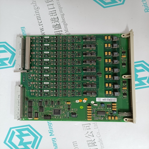
VIBRO IOCN 200-566-000-112 Vibration card
- Product ID: IOCN 200-566-000-112
- Brand: VIBRO
- Place of origin: the United States
- Goods status: new/used
- Delivery date: stock
- The quality assurance period: 365 days
- Phone/WhatsApp/WeChat:+86 15270269218
- Email:stodcdcs@gmail.com
- Tags:VIBROIOCN 200-566-000-112Vibration card
- Get the latest price:Click to consult
The main products
Spare parts spare parts, the DCS control system of PLC system and the robot system spare parts,
Brand advantage: Allen Bradley, BentlyNevada, ABB, Emerson Ovation, Honeywell DCS, Rockwell ICS Triplex, FOXBORO, Schneider PLC, GE Fanuc, Motorola, HIMA, TRICONEX, Prosoft etc. Various kinds of imported industrial parts
VIBRO IOCN 200-566-000-112 Vibration card
Each module’s voter circuits are periodically tested by the processor modules. Discrepant data are sent through one of three legs of the I/O Safetybus to determine whether the module’s voter is able to outvote the incorrect data. A failure to return the correct majority-voted result to the processors
produces an I/O module error indication at the processor modules and a module fault indication at the I/O module. Each type of module has a unique identification code that is read by the controller. This code lets the controller know which type of module is installed in each I/O chassis slot and how to address that module and its points specifically. If a module is removed, or is replaced with a module of a different type, the processor modules will indicate an I/O module error. Loopback logic tests periodically write data to the module and then read it back to determine whether the module’s I/O bus interface logic is functioning correctly. Front Panel Indicators Figure 3 shows the physical features of the analog input modules. The front panel of each module contains active and fault status indicators. Active and Fault Status Indicators These green and red LEDs indicate the overall health of the module. During normal operation the green ACTIVE indicator flashes at the controller's scan rate. If a module fault occurs the red FAULT indicator turns on and the green ACTIVE indicator turns off.
Analog Input Range Selection
The possible input voltage ranges are the same for both differential and single-ended modes. Since current measurements are converted to voltages using external precision resistors, the same voltage ranges apply. Choices of input voltage ranges include unipolar, bipolar, and offset ranges. All ranges are selected by setting jumpers located inside the module.Input Out of Range Detection If the analog signal is well beyond the normal operating range selected, the NOSIG contact associated with the analog point will be enabled. Note that there are some out-of-range signals that do not set the NOSIG bit. The out of range thresholds for each input range are shown on page 37. Absolute Signal Ranges The absolute working range for any analog input signals is from -10.3 volts to +10.3 volts with regard to AGND (analog ground). The acceptable common mode voltage range (either differential or single-ended with regard to its appropriate analog reference input) is from -10.3 volts to +10.3 volts.
When single-ended input mode is selected, the ground reference for all eight signals on the same input field wiring terminal block is AREF1 on the top terminal block and AREF2 on the bottom. This ground reference may be different from the external I/O analog ground AGND also available on the same connector. When used with the analog input terminal block assemblies (T3325-XX), both AREF1 and AREF2 are isolated from AGND by 1K Ohm resistors. When the single-ended signals are measured, the appropriate ground reference for the signal is selected by another multiplexer on the board, and becomes the reference for the measurement. In differential mode, AREF1 and AREF2 are not used as references.