Home > Product > DCS control system > HONEYWELL CC-PPIX01 Communication module
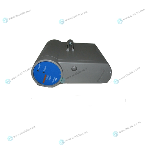
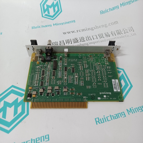
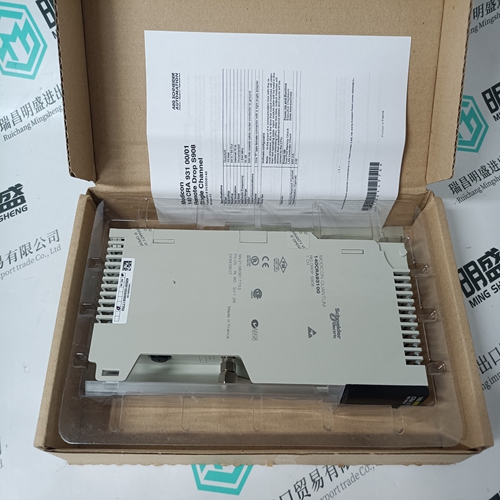
HONEYWELL CC-PPIX01 Communication module
- Product ID: CC-PPIX01
- Brand: HONEYWELL
- Place of origin: The United States
- Goods status: new/used
- Delivery date: stock
- The quality assurance period: 365 days
- Phone/WhatsApp/WeChat:+86 15270269218
- Email:stodcdcs@gmail.com
- Tags:HONEYWELLCC-PPIX01Communication module
- Get the latest price:Click to consult
HONEYWELL CC-PPIX01 Communication module
The PC830 packaging is totally enclosed single axis panel mount. The figure on the next page gives the key dimensions for use in physically mounting the product. When mounting multiple units on one panel there should be at least 20 mm (0.75") of air space on the sides and 40 mm (1.5") or air space above and below the unit.
Appendix B Servo Loop Parameters
This chapter describes setting parameters associated with the velocity and position loops. In many cases, satisfactory operation is achieved using Create New Configuration or Edit Existing Configuration buttons. However, in some cases the user must adjust control loop parameters due to large mismatches between motor and load inertia, mechanical resonance, backlash, etc. This chapter provides guidance for handling these situations. Note: The two anti-resonant zeroes (ARZ0 and ARZ1) are assumed to both be off (set to zero) for this discussion.
When mounting multiple
drives in a row some customers have found the stiffness of the drive and their mounting panel to be too low. To increase the mounted mechanical integrity, connect to the threaded insert on the top front edge. The overall drive panel dimensions and the mounted depth not including mating connectors is listed in the below chart. The extra depth for mating connectors is 1.0" or less.


Brand display
ABB、GE/FUANC、FOXBORO、TRICONEX 、BENTLY、A-B、EMERSON 、MOTOROLA、XYVOM、HONEYWELL 、REXROTH、KUKA、NI、DEIF、Yokogawa、WOODWARD、Reliance Electric、SCHNEIDER 、MOOG、PROSOFT、KOLLMORGEN、ICS TRIPLEX、HIMA
This article from the temporal Ming sheng automation equipment co., LTD., reproduced please attach this link: http://www.stockdcs.com/
