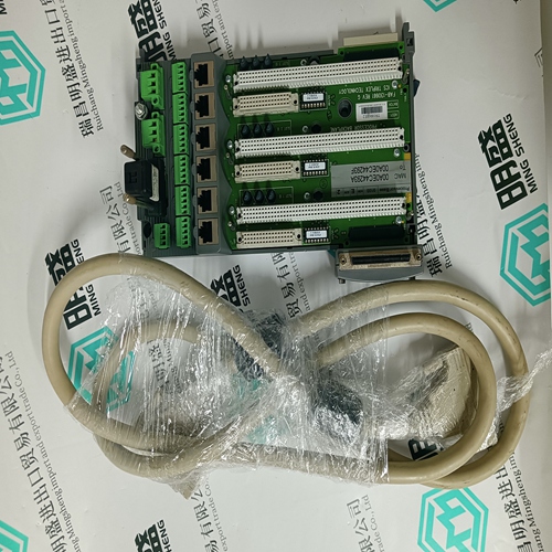
Home > Product > PLC programmable module > SST-PB3-CLX Resistance communication module
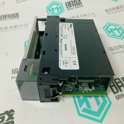
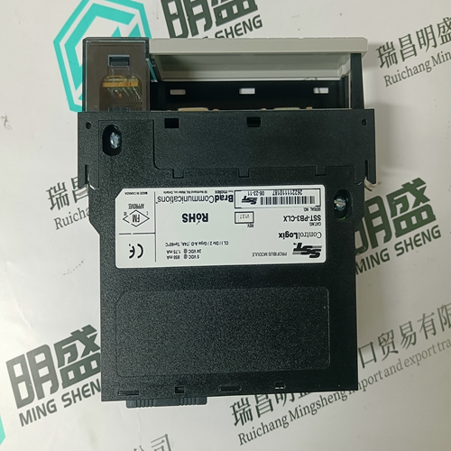
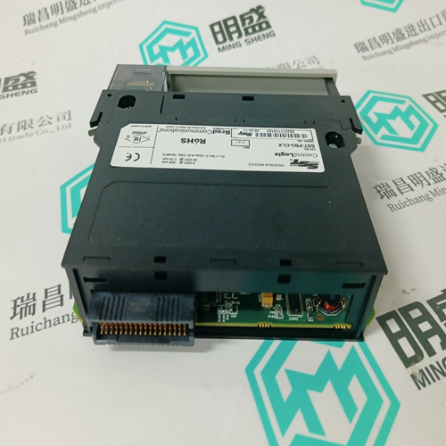
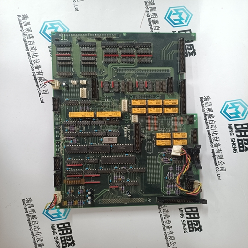
SST-PB3-CLX Resistance communication module
- Product ID: SST-PB3-CLX
- Brand: SST
- Place of origin: the United States
- Goods status: new/used
- Delivery date: stock
- The quality assurance period: 365 days
- Phone/WhatsApp/WeChat:+86 15270269218
- Email:stodcdcs@gmail.com
- Tags:SST-PB3-CLXResistance communication module
- Get the latest price:Click to consult
The main products
Spare parts spare parts, the DCS control system of PLC system and the robot system spare parts,
Brand advantage: Allen Bradley, BentlyNevada, ABB, Emerson Ovation, Honeywell DCS, Rockwell ICS Triplex, FOXBORO, Schneider PLC, GE Fanuc, Motorola, HIMA, TRICONEX, Prosoft etc. Various kinds of imported industrial parts
SST-PB3-CLX Resistance communication module
Analog input modules provide a suitable interface to noncritical input signals. Although many of the circuits in the analog input modules are automatically tested and annunciated, some logic circuits and all of the field-side sensing circuits are simplex and non-tested. This simplex input configuration is illustrated in Figure 5.For critical inputs, redundant input modules are used in a 2oo3 or 1oo2 fault tolerant configuration. In these configurations the redundant input modules are connected to single or multiple sensors. If redundant sensors are installed in the field, the redundant modules are connected so that each sensor connects to one of the redundant modules. These configurations are illustrated in Figure 6, showing triple redundant input modules. Each analog input module is hot replaceable. In redundant input configurations, if a fault occurs on one module, it can be removed and replaced while the system continues to sense the inputs from the remaining two input modules.Field wiring terminal blocks on the I/O chassis are used to connect the analog input signal wiring to the module. The terminal blocks are located directly above and below the slot where the module is installed. Each terminal block consists of 10 #6 wire clamp screw terminals capable of holding two 12 AWG wires. Figure 7 shows the proper connection of 16- channel single-ended analog input signals to the input wiring terminals. Figure 8 shows the proper connection of eightchannel differential analog input signals.
Input Low-Pass Filters
Two rows of jumper connections (J506 and J507) allow selection of onboard capacitors to create single-pole low-pass input filters on the board. Jumpers are placed on these connections to select either single-ended or differential filters as appropriate. In single-ended mode, the filtering is done with respect to the appropriate AREF1 (or AREF2) input line. A 10K Ohm resistor is in series with each analog input line (this resistor is also a part of the over voltage protection system for the module as well), and the capacitor is on the multiplexing side of the resistor. There are four rows of eight pins labeled J506 and J507, for single-ended mode filtering install jumpers across row J506 and row J507 (for a total of 16 jumpers).
In differential mode, a 10K Ohm resistor is in series with each input line of each input analog channel pair. The capacitors are placed on the multiplexing side of the resistors. The filtering is then differential. There are four rows of eight pins labeled J506 and J507, for differential mode filtering install jumpers between rows J506 and J507 (for a total of eight jumpers). Frequency response data for the T3420A and T3420AF is provided on page 37.
