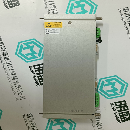
Home > Product > Robot control system > jdsu 2213-75TSLKTB Laser scanner
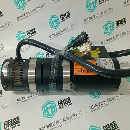
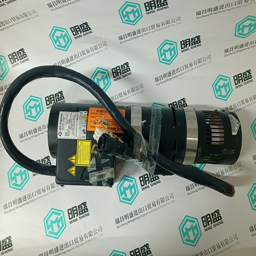
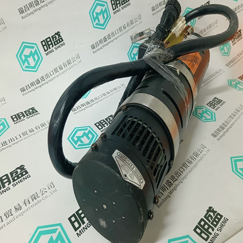
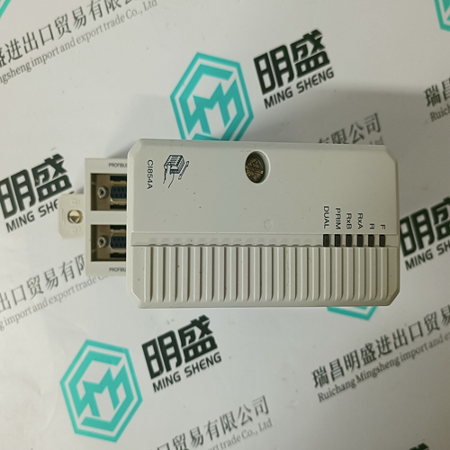
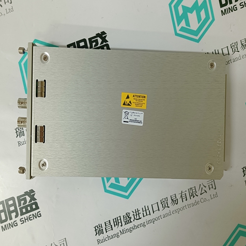
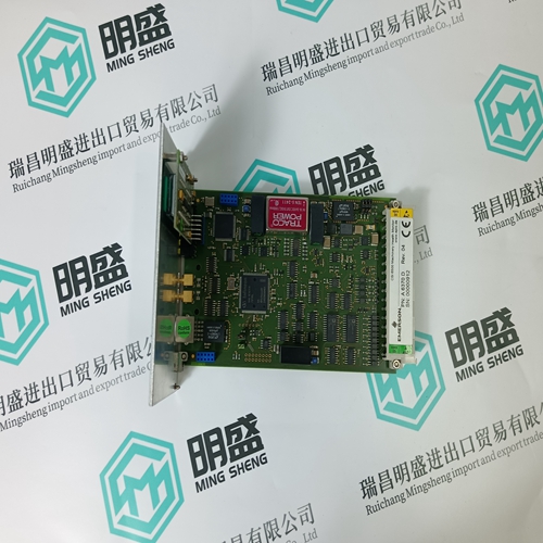
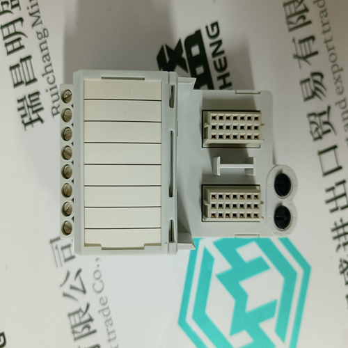
jdsu 2213-75TSLKTB Laser scanner
- Product ID: 2213-75TSLKTB
- Brand: JDSU
- Place of origin: the United States
- Goods status: new/used
- Delivery date: stock
- The quality assurance period: 365 days
- Phone/WhatsApp/WeChat:+86 15270269218
- Email:stodcdcs@gmail.com
- Tags:jdsu2213-75TSLKTBLaser scanner
- Get the latest price:Click to consult
The main products
Spare parts spare parts, the DCS control system of PLC system and the robot system spare parts,
Brand advantage: Allen Bradley, BentlyNevada, ABB, Emerson Ovation, Honeywell DCS, Rockwell ICS Triplex, FOXBORO, Schneider PLC, GE Fanuc, Motorola, HIMA, TRICONEX, Prosoft etc. Various kinds of imported industrial parts
jdsu 2213-75TSLKTB Laser scanner
These input termination block sets have high-precision resistors (250 ohms each, 0.05% initial tolerance, 5 ppm/°C drift) onboard to convert single-ended current loop signals to voltage signals that can be directly interfaced to the analog input module. Two terminals per input channel are provided where one terminal connects the active lead of the singleended current pair to the 250 ohm resistor and the other terminal connects to the analog signal return. All of the analog signal returns are commoned on the termination block and connect to the analog input module signal AREF. Model T3325-S is used for a single input module. Model T3325-SJ has additional jumper wires to connect the signals to redundant input modules installed in adjacent I/O slots. The proper wiring connections for the single-ended, current mode termination blocks are shown in Figure 12. The figure also illustrates typical marshaling terminal connections for supplying loop power from a 24 VDC power source. Differential Current Mode Input Termination Block Sets (T3325-D and -DJ) These input termination block sets service differential current-loop inputs. Each termination block has precision 250 ohm resistors (as above). Model T3325-D is used for a single input module. Model T3325-DJ has additional jumper wires to connect the signals to redundant input modules installed in adjacent I/O slots. The proper wiring connections for the differential current mode termination blocks are shown in Figure 13. The figure also illustrates typical marshaling terminal connections for supplying loop power from a 24 VDC power source.
Keying
The I/O chassis can be physically keyed to prevent accidental damage caused by inserting a module into a slot wired for a different module type. Figure 14 illustrates how the slot keys are installed on the I/O chassis slot field wiring connectors. The slot key positions for the analog input modules are listed in Table 5.
Configuration
Each input module is configured using the WINTERPRET I/O Configuration Editor. In the editor, you will perform the three steps described below to configure the input module. 1) Set the Module Type: Position the cursor on the module slot you wish to define. Choose Set Module Type from the Edit Menu and select the appropriate analog input module from the list. There are four different analog input module types listed in the Set Module Type dialog. Be sure to select the appropriate module, i.e. standard response (T3420A) vs. fast response (T3420AF) and single-ended (16-channel) vs. differential (8-channel). 2) Edit the Module Definition: Choose Edit Module Definition from the Edit Menu. A dialog box will open where you can define the input point definitions. Single-ended analog input modules will show sixteen points that you can configure, while differential analog input modules will show eight points that you can configure.
