Home > Product > DCS control system > YOKOGAWA AIP830-111 Operating keyboard
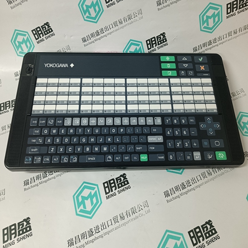
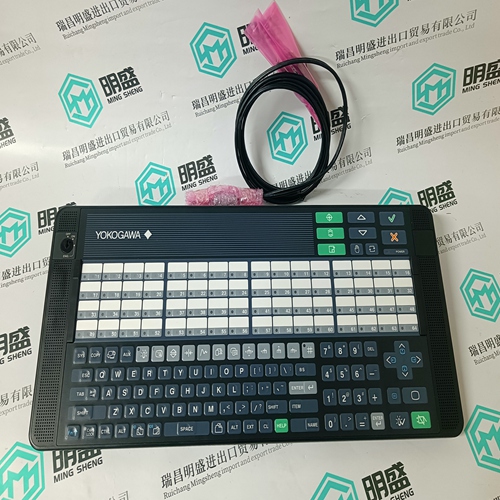
YOKOGAWA AIP830-111 Operating keyboard
- Product ID: AIP830-111
- Brand: YOKOGAWA
- Place of origin: Japan
- Goods status: new/used
- Delivery date: stock
- The quality assurance period: 365 days
- Phone/WhatsApp/WeChat:+86 15270269218
- Email:stodcdcs@gmail.com
- Tags:YOKOGAWAAIP830-111Operating keyboard
- Get the latest price:Click to consult
The main products
Spare parts spare parts, the DCS control system of PLC system and the robot system spare parts,
Brand advantage: Allen Bradley, BentlyNevada, ABB, Emerson Ovation, Honeywell DCS, Rockwell ICS Triplex, FOXBORO, Schneider PLC, GE Fanuc, Motorola, HIMA, TRICONEX, Prosoft etc. Various kinds of imported industrial parts
YOKOGAWA AIP830-111 Operating keyboard
Edit each point: Position the cursor on a Point definition and choose Edit from the Module Definition dialog box to define a name and description for each I/O point. In the Analog Input Point dialog, enter a tag name (up to 12 characters) and a description (up to 40 characters). The tag names are used in the application program to represent the value of the analog input in your control algorithms and interlocks.Programming Inputs are referenced in the application program through the tag names defined in the I/O Configuration Editor. The analog inputs will range in value from 0 to 4095 over the voltage range configured for the analog input module. Most often you will want to scale the analog input values to a more convenient engineering unit number range.
Scaling Analog Inputs The scaling function block is used to convert the raw 0 to 4095 units of the analog input to an engineering unit number. The result of this scaling conversion is usually stored in a shared variable register that you define in the shared variable editor. After scaling the analog input to a register, you can use the register tag name in your applications to work with the process variable in engineering units. An example of an analog scaling entry is shown in Figure 17. For more details about configuring analog scaling function blocks refer to Using the Analog Scaling Editor in Section 5 Working with Programs and Function Blocks in the Regent User’s Guide.
Maintenance
There are no user-replaceable parts inside the module. Modules must be calibrated for the particular input range within which they will operate. All modules are calibrated before being shipped by ICS; however, modules require calibration whenever: · the module is configured for a different operating voltage range (factory configuration is 1 to 5 VDC), · the module is configured for a different operating mode (factory configuration is 16 channel, single-ended), or · once per year after installation, to adjust for drift in the analog circuitry. Drift rates are listed under Specifications, below. These drift rates should be used to help you determine the frequency for checking the calibration of the modules in your installation. In this illustration, VALUE_A_NAME, VALUE_B_NAME, and VALUE_C_NAME represent the three analog inputs to be mid-value selected. ERROR_A_NAME, ERROR_B_NAME and ERROR_C_NAME are the error bits for the analog inputs. RESULT_NAME is the result of the mid-value instruction. The field Limit is the integer value, in similar units to the Value A, B and C variables, that an analog input can deviate from the mid-value result before signaling an error (via the Error A, B or C bits). Once an error bit is set, it is latched. RESET_NAME is the reset bit used to reset the latched error bits.