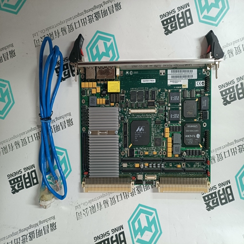
Home > Product > Robot control system > UNIOP TCM08A communication card
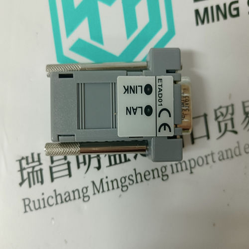
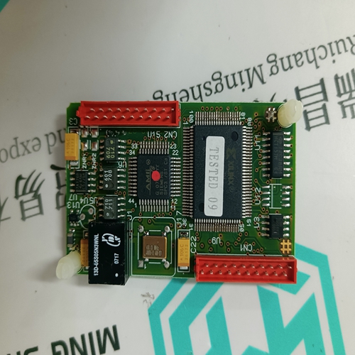
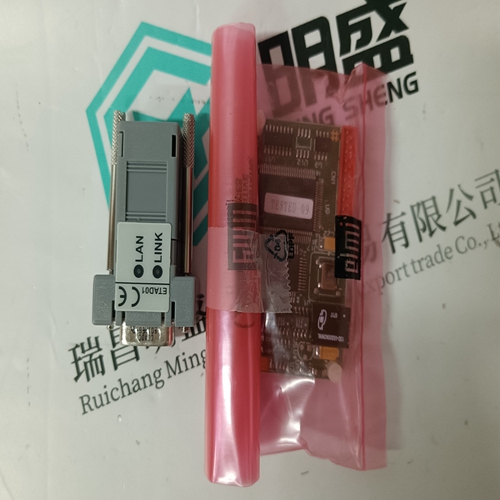
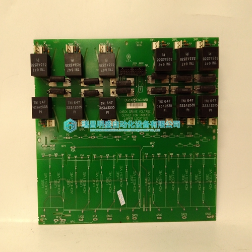
UNIOP TCM08A communication card
- Product ID: TCM08A
- Brand: UNIOP
- Place of origin: the United States
- Goods status: new/used
- Delivery date: stock
- The quality assurance period: 365 days
- Phone/WhatsApp/WeChat:+86 15270269218
- Email:stodcdcs@gmail.com
- Tags:UNIOPTCM08Acommunication card
- Get the latest price:Click to consult
The main products
Spare parts spare parts, the DCS control system of PLC system and the robot system spare parts,
Brand advantage: Allen Bradley, BentlyNevada, ABB, Emerson Ovation, Honeywell DCS, Rockwell ICS Triplex, FOXBORO, Schneider PLC, GE Fanuc, Motorola, HIMA, TRICONEX, Prosoft etc. Various kinds of imported industrial parts
UNIOP TCM08A communication card
The I/O extender module has jumper posts that allow you to connect or disconnect the I/O slot field wiring on the I/O chassis to the printed circuit board plugged into the I/O extender. During the calibration steps you will remove any jumpers installed on these posts in order to connect the DC voltage signal source to the analog inputs. For modules configured for 16-channel, single-ended inputs, Figure 20 shows the jumper posts to which you should connect the signal source for each analog input channel. For modules configured for 8-channel, differential inputs, Figure 21 shows the jumper posts to which you should connect the signal source for each analog input channel.
Within each pair of jumper posts, make sure that you connect the voltage source to the jumper posts nearest the front of the I/O extender. Do not make any connections to the jumper posts nearest the I/O chassis backplane — these connect to the actual field wiring attached to the I/O slot terminals on the I/O chassis.clamshell housing. Remove the I/O extender module from the I/O chassis and reinstall the calibrated module in the I/O chassis. The module’s red Fault indicator will be on until you perform a voted reset by pressing the Reset buttons on two of the Regent processor modules. After the voted reset is complete, the module’s green Active indicator should turn on.
Calibration Steps
1. Remove the module to be calibrated from the I/O chassis. 2. Install the I/O extender module into the slot from which the module was removed. 3. Remove the jumpers (if installed) labeled CH1 through CH16 from the I/O extender module.4. Connect the DC voltage signal source to the I/O extender jumper posts as shown in Figures 20 or 21. Use test clips as required to make the connections. 5. Remove the four screws on one side of the module and remove the printed circuit board from the module clamshell housing. 6. Install the printed circuit board into the I/O extender module. Allow the board to warm up for approximately one minute. 7. Adjust the DC voltage source to the Offset Input Voltage value indicated in Table 6 for the configured input range of the input module. Wait approximately one minute for the analog inputs to stabilize. 8. Using the monitoring functions of WINTERPRET, monitor the values of all the analog input channels. Refer to the Regent User’s Guide for more details about the monitoring functions. 9. Adjust the Offset potentiometer (R569) for an average reading of 2 ±1 for all input channels. Verify that all input channels read between 1 and 3. If one or more channels reads significantly different, return the module to ICS for repair. 10.Adjust the DC voltage source to the Gain Input Voltage value indicated in Table 6 for the configured input range of the input module. Wait approximately one minute for the analog inputs to stabilize. 11.Adjust the Gain potentiometer for a reading of 4093 ±1 for all channels. Verify that all input channels read between 4092 and 4094. If one or more channels reads significantly different, return the module to ICS for repair. 12.Repeat steps 7 through 11 and make adjustments if necessary until both the Offset and Gain values read correctly. There is some interaction between the Offset and Gain adjustments so often you will need to repeat these steps a few times until both the Offset and Gain readings read correctly without further adjustments. 13.Calibration is complete. Unplug the printed circuit board from the I/O extender module and replace it in its
