Home > Product > PLC programmable module > EX2100 Excitation module
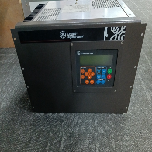
EX2100 Excitation module
- Product ID: EX2100
- Brand: GE
- Place of origin: the United States
- Goods status: new/used
- Delivery date: stock
- The quality assurance period: 365 days
- Phone/WhatsApp/WeChat:+86 15270269218
- Email:stodcdcs@gmail.com
- Tags:EX2100Excitation module
- Get the latest price:Click to consult
The main products
Spare parts spare parts, the DCS control system of PLC system and the robot system spare parts,
Brand advantage: Allen Bradley, BentlyNevada, ABB, Emerson Ovation, Honeywell DCS, Rockwell ICS Triplex, FOXBORO, Schneider PLC, GE Fanuc, Motorola, HIMA, TRICONEX, Prosoft etc. Various kinds of imported industrial parts
EX2100 Excitation module
If all points have been calibrated and verified, press EXIT button to leave calibration mode and enter operation mode. If additional function blocks are to be calibrated and verified, press STEP UP button to enter FUNCTION BLOCK level. Perform steps 2-19 for each function block. If security is enabled, the exiting the configuration mode will lock out the calibration mode until the security combination is re-entered.
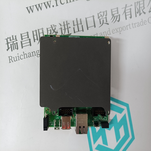
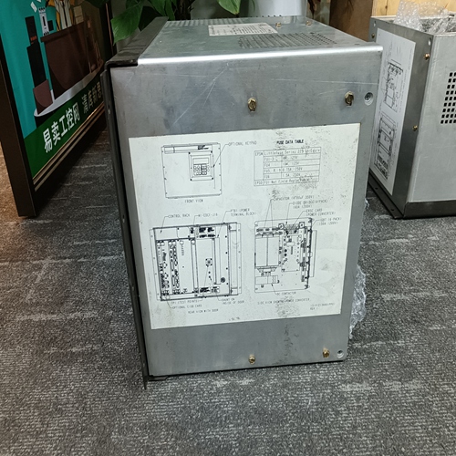
13.0 CIRCUIT DESCRIPTION This section provides a block diagram level circuit description of the Moore 353. 13.1 OVERVIEW Controller hardware architecture is shown in Figure 13-1. Notice that all major plug-in assemblies interact with the Controller Board. The Display Assembly is used for operation and configuration. The MPU-based Controller Board performs many of the controller’s signal processing and process control functions in addition to overseeing internal operations. The Controller Board’s on-board power supply furnishes DC operating voltages to all plug-in assemblies and to external process transmitters connected to the rear terminals. The I/O Expander board provides additional I/O. Networking options include Modbus, Local Instrument Link and Ethernet.
MPU CONTROLLER BOARD
The heart of the 353 is the powerful, microprocessor-based MPU Controller Board. The flexible software supports reusable function blocks beneficial in solving a vast array of control strategies such as single loop, cascade and dual loop. The Controller Board assembly contains both analog and digital circuits. The analog circuitry operates in real time while the microprocessor based digital circuitry operates at high speed under program control. The MPU (microprocessor unit) contains a CPU32 core, System Integration Module (SIM), a queued SPI module (QSPI), timer module and two general-purpose 8-bit ports. The MPU is capable of arithmetic, logical, and support circuit control functions and interacts with surrounding on-board and off-board circuitry to control the internal operation of the 353. The MPU Board also contains 16-bit RAM, 16-bit ROM, a 2-wire RS485 connection, and an RS232 connection. The CPU32 communicates with the RAM, ROM and external communications boards via the SIM. All communication between the MPU and the I/O, display and expander board is done via the QSPI. The QSPI is a full-duplex, synchronous serial interface with a queue for receive and transmit data. Communication consists of timing, control, data, and sequencing information. The Controller Board has three analog inputs, 3 digital inputs, 2 analog outputs and 2 digital outputs. The configuration in use determines the active inputs and outputs. For example, Factory Configured Option FCO101 is configured to accept one analog input for the process signal and one analog output for the valve signal. The two analog outputs are 4 to 20 mA current sources with shutdown control for use in redundant control systems. The two digital outputs are open collector devices with over-voltage protection.