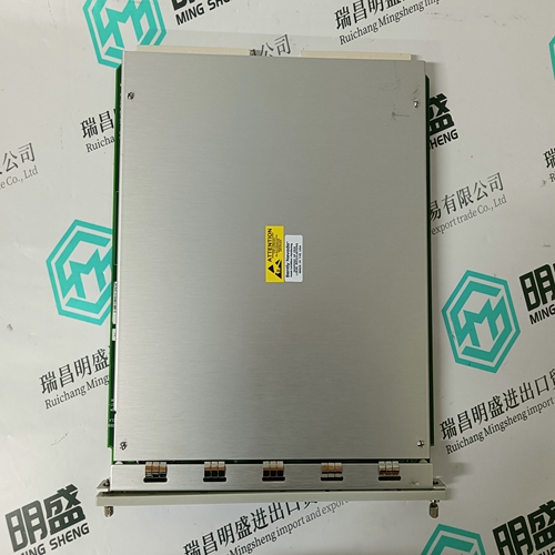
Home > Product > PLC programmable module > BENTLY 136719-01 displacement module
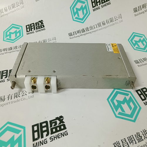
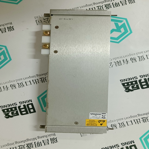
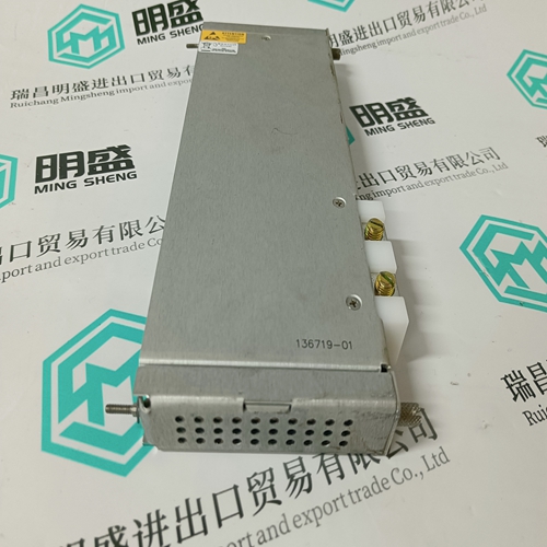
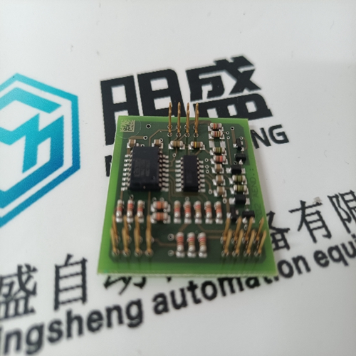
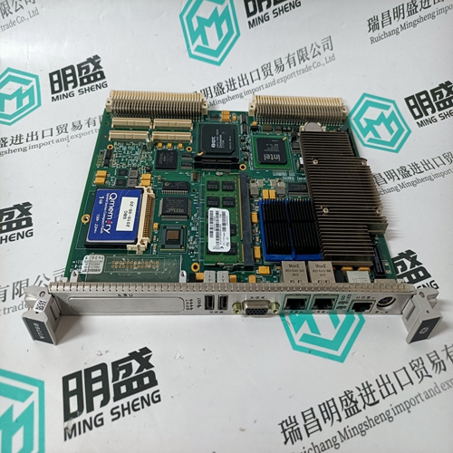
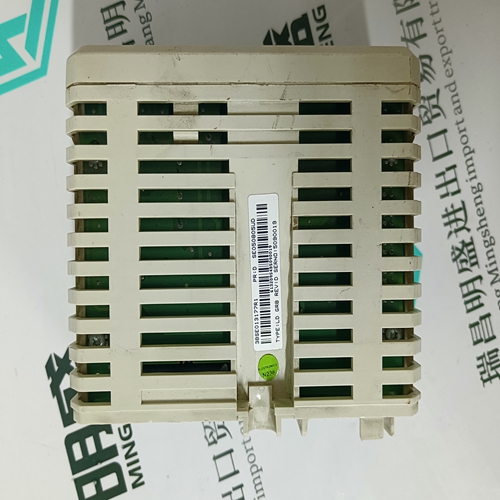
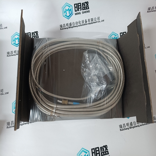
BENTLY 136719-01 displacement module
- Product ID: 136719-01
- Brand: BENTLY
- Place of origin: the United States
- Goods status: new/used
- Delivery date: stock
- The quality assurance period: 365 days
- Phone/WhatsApp/WeChat:+86 15270269218
- Email:stodcdcs@gmail.com
- Tags:BENTLY136719-01displacement module
- Get the latest price:Click to consult
The main products
Spare parts spare parts, the DCS control system of PLC system and the robot system spare parts,
Brand advantage: Allen Bradley, BentlyNevada, ABB, Emerson Ovation, Honeywell DCS, Rockwell ICS Triplex, FOXBORO, Schneider PLC, GE Fanuc, Motorola, HIMA, TRICONEX, Prosoft etc. Various kinds of imported industrial parts
BENTLY 136719-01 displacement module
System Reset: A System Reset establishes the following board status: Automatic scanning of all channels Front panel diagnostic LED indicator ON Offset Binary Data Format Front Panel System Diagnostic LED: A software-controlled front panel LED turns ON at System Reset, and can be turned OFF under software control to provide an external indication that Built-in-Test has been completed. Analog Input Data Format: Analog inputs are digitized and stored in 32 dual-ported Data Registers (16 registers for differential operation) as 12-bit right-justified digital values. Software-selectable data codes are Offset Binary and Two’s Complement. In two’s complement coding, the sign bit (D11) is extended through the most significant bits of the Data Register (D12 through D15). SPECIFICATIONS (At +25 °C and rated power supplies unless otherwise noted.) INPUT CHARACTERISTICS Number of Channels: 32 single-ended or 16 differential voltage input channels 32 single-ended current input channels Voltage Ranges: ±50 mV to ±10 V, bipolar: or 0 to +100 mV, 0 to +10 V unipolar.1 Factory configured for ±10 V input range. Current Termination: 250 Ω 0.01% 500 Ω 0.01% Current Ranges: 0 to 20 mA 4 to 20 mA 5 to 25 mA Input Impedance: For voltage input options, 10 MΩ minimum, line-to-line and line-to-common2 Common-Mode Voltage (CMV): ±11 V,
Validity of the documentation
This documentation is valid for the following products: • VT-VPCD-1-1X/V0/1-0-1, material number R901044346 • VT-VPCD-1-1X/V0/1-C-1, material number R901102344 • VT-VPCD-1-1X/V0/1-D-1, material number R901102347 • VT-VPCD-1-1X/V0/1-P-1, material number R901089559 • VT-VPCD-1-1X/V100/1-0-1, material number R901078493 This documentation is intended for fitters, operators, service technicians and plant operators. This documentation contains important information on the safe and appropriate installation, transport, commissioning, maintenance, operation, removal and simple troubleshooting of the product. ▶ Read this documentation thoroughly, especially Chapter 2 “Safety instructions“ and Chapter 3 “General notes on damage to property and damage to the product“ before working with the digital control electronics VT-VPCD.
In order to allow you to work directly and safely with your product, standardized safety notes, symbols, terms and abbreviations are used. For a better understanding, these are explained in the following sections. 1.3.1 Safety notes This documentation contains safety notes in Chapter 2.6 “Product-specific safety instructions“ and Chapter 3 “General notes on damage to material and the product“ as well as before a sequence of activities or instructions for action, which involve the risk of personal injury or damage to equipment. The measures described for averting the hazard must be observed.
