Home > Product > Gas turbine system > GE DS200SDCCG4AFD Channel relay module
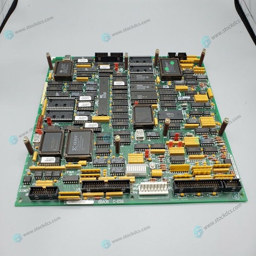
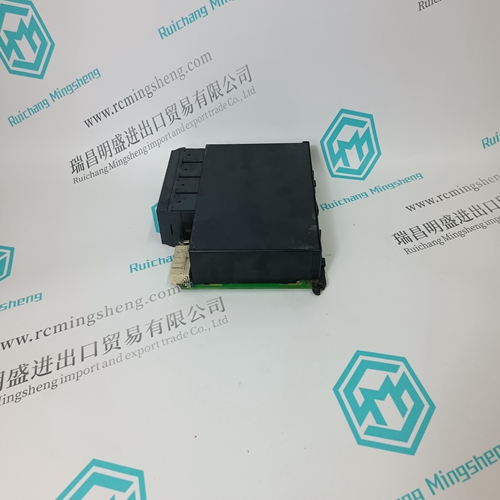
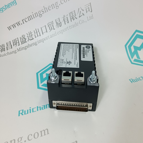
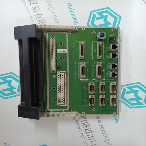
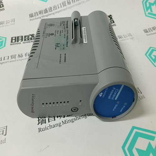
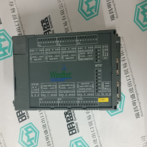
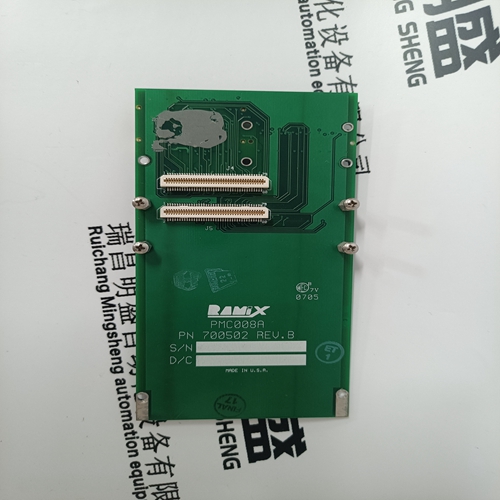
GE DS200SDCCG4AFD Channel relay module
- Product ID: DS200SDCCG4AFD
- Brand: GE
- Place of origin: The United States
- Goods status: new/used
- Delivery date: stock
- The quality assurance period: 365 days
- Phone/WhatsApp/WeChat:+86 15270269218
- Email:stodcdcs@gmail.com
- Tags:GEDS200SDCCG4AFDChannel relay module
- Get the latest price:Click to consult
GE DS200SDCCG4AFD Channel relay module
The two pins of each socket on a test fixture board which make up the reference pin pair are (1) the socket pin with the shortest wiring path to the pulse generation circuit (Terminal B) and (2) the socket pin with the longest wiring path from the pulse generation circuit (Terminal A) to the ESD stress socket. (See Figure 1). This information is typically provided by the equipment or test fixture board manufacturer. If more than one pulse generation circuit is connected to a socket then there may be more than one reference pin pair
Waveform Capture with Current Probe
To capture a current waveform between two socket pins (usually the reference pin pair), use the shorting wire (Section 4.1.3, Load 1) for the short circuit measurement or the 500 ohm resistor (Section 4.1.3, Load 2) for the 500 ohm current measurement and the inductive current probe It is recommended that on non-positive clamp fixtures, feed through test point pads be added on these paths. These test points should be added as close as possible to the socket(s). NOTE: A positive clamp test socket is a zero insertion force (ZIF) socket with a clamping mechanism. It allows the shorting wire to be easily clamped into the socket. Examples are dual in-line package (DIP) and pin grid array (PGA) ZIF sockets.


Our products
A company specializes in the sales of module spare parts of global famous brands (DCS system) (robot system) (large servo control system). The company's products include distributed control system (DCS), programmable controller (PLC), MOTOROLA MVME industrial module, industrial control communication converter (Anybus), remote output/input module (RTU), industrial computer (IPC), industrial low screen screen (IPC) HMI SCSI (50, 68, 80Pin) AnyBus (Gateway) has become a global sales enterprise of industrial automation spare parts and components
This article from the temporal Ming sheng automation equipment co., LTD., reproduced please attach this link: http://www.stockdcs.com/
