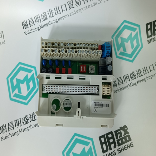
Home > Product > DCS control system > EPRO MMS3120/022-000 front sensor
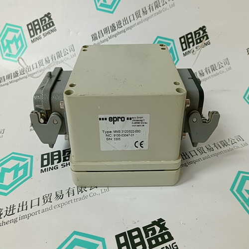
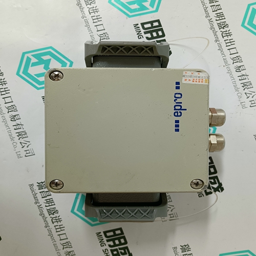
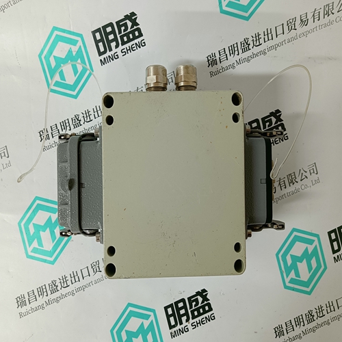
EPRO MMS3120/022-000 front sensor
- Product ID: MMS3120/022-000
- Brand: EMERSON
- Place of origin: The United States
- Goods status: new/used
- Delivery date: stock
- The quality assurance period: 365 days
- Phone/WhatsApp/WeChat:+86 15270269218
- Email:stodcdcs@gmail.com
- Tags:EPROMMS3120/022-000front sensor
- Get the latest price:Click to consult
The main products
Spare parts spare parts, the DCS control system of PLC system and the robot system spare parts,
Brand advantage: Allen Bradley, BentlyNevada, ABB, Emerson Ovation, Honeywell DCS, Rockwell ICS Triplex, FOXBORO, Schneider PLC, GE Fanuc, Motorola, HIMA, TRICONEX, Prosoft etc. Various kinds of imported industrial parts
Products are widely used in metallurgy, petroleum, glass, aluminum manufacturing, petrochemical industry, coal mine, papermaking, printing, textile printing and dyeing, machinery, electronics, automobile manufacturing, tobacco, plastics machinery, electric power, water conservancy, water treatment/environmental protection, municipal engineering, boiler heating, energy, power transmission and distribution and so on.
EPRO MMS3120/022-000 front sensor
• The status LED (red) of the analog output will flash to indicate “manual override.” When a manual override of the XFR822/XFLR822 is set to 0…100%, and the corresponding analog output has not been configured, the following applies: • The output voltage of the analog output will be 0…10 V. • The feedback signal on the LONWORKS network nvoAoActPosnFb[ ] will have a value of 0…100% and a state of -1. • The status LED (red) of the analog output will flash to indicate “manual override.” Analog Outputs Configured as Binary Outputs Using CARE, the analog outputs can be configured individually as binary outputs. The voltage output is then 0 V or 10 V, depending upon the signal from the controller.Synchronization Behavior of Analog Output Module Configured as Floating Output In order to regularly update the real actuator position with the calculated position and thus ensure that the actuator definitely reaches its end position, a synchronization process is performed by the analog output module. During the synchronization process, the analog output module will continue running for the configured runtime once it reaches the calculated end position.
This updating (synchronization) is performed
• If the calculated position of the actuator < lower synchronization threshold (2%) = synchronization towards 0% • If the calculated position of the actuator > upper synchronization threshold (98%) = synchronization towards 100% • Following any power-up or any reset • The relay module facilitates the control of peripheral devices with high load via the analog outputs. • Input terminal 17 controls of MCD3 controls changeover contact K3. • Relay terminal 18 of MCD3 controls the N.O. contacts (floating outputs) K1, K2. For fusing specifications, see section "Fusing Specifications" on page 10.he relay module facilitates the control of peripheral devices with high load via the analog outputs. • Input terminal 16 of MCE3 controls the N.O. contact K3. • Input terminal 17 of MCE3 controls the changeover contact K2. • Input terminal 18 of MCE3 controls the changeover contact K1. For fusing specifications, see section "Fusing Specifications" on page 10.Features • 12 binary inputs • 12 configurable status LEDs (green/red, yellow/OFF) • Binary inputs can be used as – Static digital inputs as dry-contacts (default) – Fast totalizers (up to 20 Hz)
