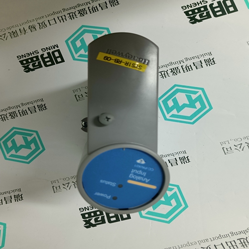
Home > Product > DCS control system > PPC380AE01 HIEE300885R0001 controller
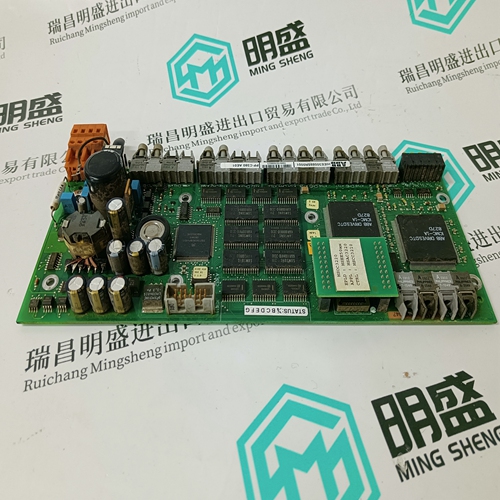
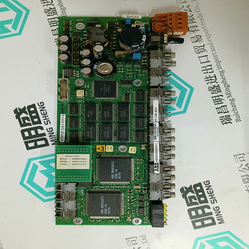
PPC380AE01 HIEE300885R0001 controller
- Product ID: PPC380AE01 HIEE300885R0001
- Brand: ABB
- Place of origin: The Swiss
- Goods status: new/used
- Delivery date: stock
- The quality assurance period: 365 days
- Phone/WhatsApp/WeChat:+86 15270269218
- Email:stodcdcs@gmail.com
- Tags:PPC380AE01 HIEE300885R0001controller
- Get the latest price:Click to consult
The main products
Spare parts spare parts, the DCS control system of PLC system and the robot system spare parts,
Brand advantage: Allen Bradley, BentlyNevada, ABB, Emerson Ovation, Honeywell DCS, Rockwell ICS Triplex, FOXBORO, Schneider PLC, GE Fanuc, Motorola, HIMA, TRICONEX, Prosoft etc. Various kinds of imported industrial parts
Products are widely used in metallurgy, petroleum, glass, aluminum manufacturing, petrochemical industry, coal mine, papermaking, printing, textile printing and dyeing, machinery, electronics, automobile manufacturing, tobacco, plastics machinery, electric power, water conservancy, water treatment/environmental protection, municipal engineering, boiler heating, energy, power transmission and distribution and so on.
PPC380AE01 HIEE300885R0001 controller
• Shield connection to be used for shielded I/O cables only. It is not allowed to connect a LONWORKS shield, since LONWORKS requires a resistor and capacitor. • If additional shield terminals are needed, the XS814 Auxiliary Terminal Package can be installed.Status LED Behavior Using CARE, each of the twelve status LEDs can be configured individually for use as either alarm LEDs (red/green) or as status LEDs (yellow/OFF [default]). Given a logical state of "ON," the status LED will be lit (yellow or red).
In the event of communication problems, the relay outputs will move to the safety positions you have configured in CARE, see relay output point description in the CARE – User Guide, EN2B-0182GE51 / 74-5587. WARNING Risk of electric shock or equipment damage! Low voltage and line voltage must not be wired within the same relay block. ► Wire low voltage e.g., to relay block 1 and line voltage to relay block 2 or vice versa. In this case, the short cross connectors must be used, see Table 5 on page 7. NOTICE Risk of malfunction! Cross connectors may only be used if the same voltage is used on all relays they connect. ► Do not use a cross connector if different voltages are used on the relays. E.g., use a short cross connector for relay block 1 with line voltage and no cross connector for relay block 2 with 12 V low voltage for relay 4 and 24 V low voltage for relays 5 and 6.
Manual Override in the AUTO Position
When a manual override of the …R824 Relay Output Module is set to the “AUTO” position, and the corresponding relay output has been configured, the following applies: • If the LONWORKS network is functioning properly, the logical status of the relay output will be “AUTO.” • If the LONWORKS network is not functioning properly, the feedback signal will be switched to the safety position value. • The feedback signal on the LONWORKS network: nvoDoActPosnFb[ ] will have a value of either 0% or 100%, and a state of -1. • The status LED (yellow) will indicate the actual logical state of the relay output as commanded (by nviDoSwitch[ ]). When a manual override of the …R824 Relay Output Module is set to the “AUTO” position, and the corresponding relay output has not been configured, the following applies: • Regardless as to whether the LONWORKS network is functioning properly or not, values from the LONWORKS Bus will be ignored, and there will be no heartbeat or safety position. • The feedback signal on the LONWORKS network: nvoDoActPosnFb[ ] will have a value of 0% and a state of 0. • The status LED will be unlit.
