Home > Product > DCS control system > UBC717BE101 3BHE021887R0101 Output module
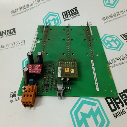
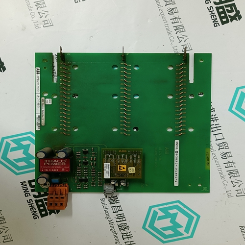
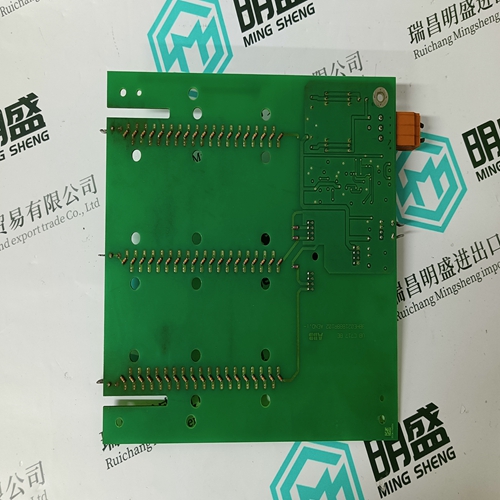
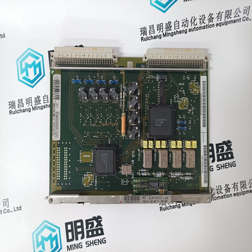
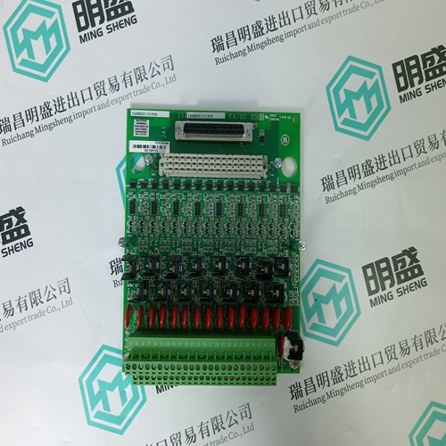
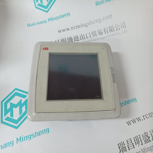
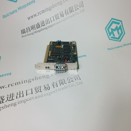
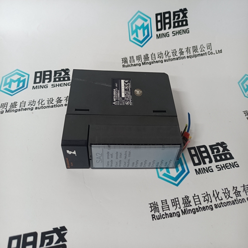
UBC717BE101 3BHE021887R0101 Output module
- Product ID: UBC717BE101 3BHE021887R0101
- Brand: ABB
- Place of origin: The Swiss
- Goods status: new/used
- Delivery date: stock
- The quality assurance period: 365 days
- Phone/WhatsApp/WeChat:+86 15270269218
- Email:stodcdcs@gmail.com
- Tags:UBC717BE101 3BHE021887R0101Output module
- Get the latest price:Click to consult
The main products
Spare parts spare parts, the DCS control system of PLC system and the robot system spare parts,
Brand advantage: Allen Bradley, BentlyNevada, ABB, Emerson Ovation, Honeywell DCS, Rockwell ICS Triplex, FOXBORO, Schneider PLC, GE Fanuc, Motorola, HIMA, TRICONEX, Prosoft etc. Various kinds of imported industrial parts
Products are widely used in metallurgy, petroleum, glass, aluminum manufacturing, petrochemical industry, coal mine, papermaking, printing, textile printing and dyeing, machinery, electronics, automobile manufacturing, tobacco, plastics machinery, electric power, water conservancy, water treatment/environmental protection, municipal engineering, boiler heating, energy, power transmission and distribution and so on.
UBC717BE101 3BHE021887R0101 Output module
Features • Type: XS814 Auxiliary Terminal Package • For mounting onto already-installed pluggable I/O modules in order to equip them with additional terminals. • Each unit consists of two terminal blocks (the "A" block and the "B" block), each with seven terminals with a maximum load of 12 A.• Type: XS830 Auxiliary Terminal Package • For mounting onto the top and/or bottom of alreadyinstalled XF830A mixed I/O modules and the top of already-installed XFU830A mixed I/O modules in order to equip them with additional terminals. • Each unit consists of two groups of terminal blocks (the "A" block and the "B" block), each with nine internally-connected push-in terminals with a maximum load of 12 A.Type: XS831 Auxiliary Terminal Package • For mounting onto the top and/or bottom of alreadyinstalled XF830A mixed I/O modules and the top of already-installed XFU830A mixed I/O modules in order to equip them with additional terminals. • Two groups of four pairs of push-in terminals (A1B1, A2B2, … A8B8, each with a 499Ω resistor) for converting 0…20 mA signals (maximum load per resistor = 25 mA) into 0…10 Vdc signals, and one push-in ground terminal per group. See also Fig. 88 and Fig. 89. Note The ground side of each of the eight incoming 0…20 mA signals (A1B1, A2B2, … A8B8) must be connected to a ground terminal.
Configured Floating Relay Output
If a floating relay output has been configured, the following applies: The corresponding manual override can be used to adjust the respective floating actuator so that it drives to any desired position between fully closed (0%) and fully open (100%). The "open" relay or "closed" relay – as the case may be – is then switched ON for the time the actuator requires to drive to the desired position, whereupon it will stop. This required time depends upon the configured motor runtime (time to open / time to close,) while the direction of movement is dependent upon the configured direct/reverse setting.If a floating relay output has not been configured (see Fig. 83), the following applies: Although the motor runtime is unknown to the XFR825, the corresponding manual override can be used during the commissioning phase to adjust the respective floating actuator so that it drives to any desired position between fully closed (0%) and fully open (100%). The "open" relay (relay "n," i.e. “1,” “3,” or “5”) and the "closed" relay (relay "n+1," i.e. “2,” “4,” or “6”) are then switched ON and/or OFF, respectively, when the corresponding manual override is set to "0…100%." Specifically, the actuator will drive towards its closed position as long as the manual override is set to "0…50%," and it will drive towards its open position as long as it is set to "50…100%." Setting the manual override to "AUTO" stops the actuator.
