Home > Product > Gas turbine system > GE DS215TCCBG3AZZ01A Remote control module
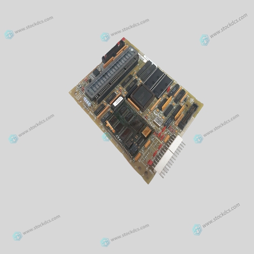
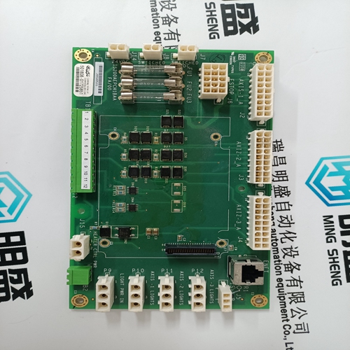
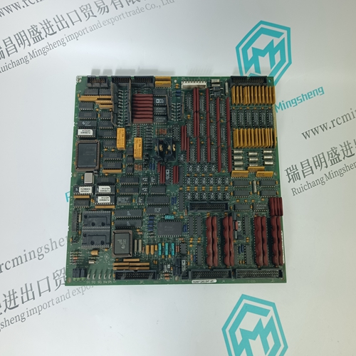
GE DS215TCCBG3AZZ01A Remote control module
- Product ID: DS215TCCBG3AZZ01A
- Brand: GE
- Place of origin: The United States
- Goods status: new/used
- Delivery date: stock
- The quality assurance period: 365 days
- Phone/WhatsApp/WeChat:+86 15270269218
- Email:stodcdcs@gmail.com
- Tags:GEDS215TCCBG3AZZ01ARemote control module
- Get the latest price:Click to consult
GE DS215TCCBG3AZZ01A Remote control module
Good procedure suggests that the system should be tested each time a new application is powered up. The DIAG LED on the MMC should be off indicating that the diagnostic tests were passed. Turn off the main disconnect switch and plug the DC connector into the power connector. Turn on input power. The DIAG LED turns on and then turns off when the MMC passes its diagnostic tests.
Connecting the MMC to the Application
1. Turn off the main disconnect switch in the control cabinet. If some devices are not powered from the control cabinet, turn them off also. 2. Connect the connectors according to your diagrams. 3. Turn on power to the system. The PWR light goes on and stays on. The DIAG light goes on, then goes off in turn. The SCAN light goes on. The application starts to work under control of the system. 4. If an application program is not in system memory, use the download command in the PiCPro software to place it there.


Do you want to know about our products?
We have a large amount of inventory and high quality, out of production control system components, DCS system accessories, robot system accessories, large servo system spare parts. PLC module, DCS module, CPU module, IO module, DO module, AI module, DI module, network communication module, Ethernet module, motion control module, analog input module, analog output module, digital input module, digital output module, redundancy module, power module, relay output module, relay input module, processor module and other major brands.
This article from the temporal Ming sheng automation equipment co., LTD., reproduced please attach this link: http://www.stockdcs.com/
