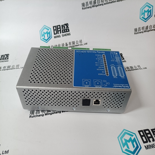
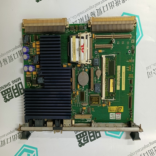
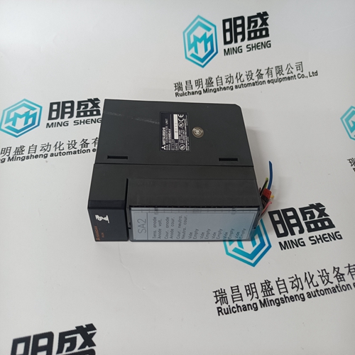
Home > Product > Robot control system > ALSTOM MAVS01L1AB0501D Relay module
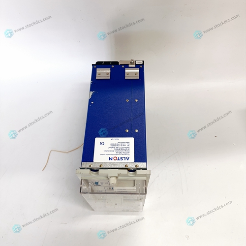
ALSTOM MAVS01L1AB0501D Relay module
- Product ID: MAVS01L1AB0501D
- Brand: ALSTOM
- Place of origin: The United States
- Goods status: new/used
- Delivery date: stock
- The quality assurance period: 365 days
- Phone/WhatsApp/WeChat:+86 15270269218
- Email:stodcdcs@gmail.com
- Tags:ALSTOMMAVS01L1AB0501DRelay module
- Get the latest price:Click to consult
ALSTOM MAVS01L1AB0501D Relay module
Lambda-EMI does not recommend connecting more than two ESS power supplies in parallel. Contact the factory before connecting three or more supplies in parallel. 1) The J1 programming connector should be configured before connecting the two power supplies in parallel. Caution: Verify that step 1 is done properly before proceeding. 2) Advance the Current control of each supply one half turn clockwise. 3) Use the Voltage control on each unit to set the required output voltage
Turn off both power supplies
rotate each Current control to its maximum counterclockwise position. 5) Connect each positive load terminal to the positive side of the load. Connect each negative load terminal to the negative side of the load. NOTE: Individual leads between the power supply and load must be equal in length and of sufficient gauge to provide a low impedance. 6) Turn both power supplies on. 7) Use the Voltage controls to ensure that each power supply delivers approximately the same load current. 8) Slowly adjust each Current control to limit supply output current just above the value required by the load.


Do you want to know about our products?
We have a large amount of inventory and high quality, out of production control system components, DCS system accessories, robot system accessories, large servo system spare parts. PLC module, DCS module, CPU module, IO module, DO module, AI module, DI module, network communication module, Ethernet module, motion control module, analog input module, analog output module, digital input module, digital output module, redundancy module, power module, relay output module, relay input module, processor module and other major brands.
This article from the temporal Ming sheng automation equipment co., LTD., reproduced please attach this link: http://www.stockdcs.com/
