Home > Product > Robot control system > GEC ALSTHOM MVAX12B1DA0753A Channel input module
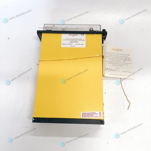
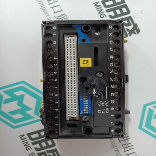
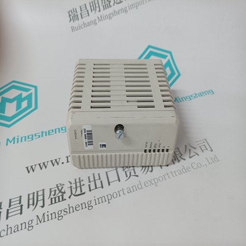
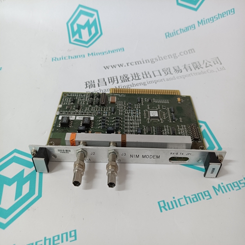
GEC ALSTHOM MVAX12B1DA0753A Channel input module
- Product ID: MVAX12B1DA0753A
- Brand: GEC ALSTHOM
- Place of origin: The United States
- Goods status: new/used
- Delivery date: stock
- The quality assurance period: 365 days
- Phone/WhatsApp/WeChat:+86 15270269218
- Email:stodcdcs@gmail.com
- Tags:GEC ALSTHOMMVAX12B1DA0753AChannel input module
- Get the latest price:Click to consult
GEC ALSTHOM MVAX12B1DA0753A Channel input module
The full bridge inverter consists of four IGBTs. T1 is designed such that Q1 and Q4 are turned on simultaneously while Q2 and Q3 are turned off. T2 senses the switching of the IGBTs and the switching of the HF power transformer's primary current. CR9, CR10, CR11, and CR12 rectify the signal from T2 and generate a voltage across the burden resistor R14. The signal across R14 is connected to the A100 card for control purposes. C5 snubs the spikes generated by the primary leakage inductance of the HF power transformer. CR2, CR4, CR6 and CR8 are the anti-parallel diodes across the switches.
The RC snubber across the device limits
the dv/dt so that latching of the IGBTs is prevented. L1, C13 and C14 form a bypass circuit which delivers the entire pulse current of the inverter, thereby reducing the area of high frequency pulse current. The signal from TS1 shuts the PWM down in case of over heating. The A100 board controls steady state volt-second balance across the high frequency power transformer to prevent saturation of T1.


Do you want to know about our products?
We have a large amount of inventory and high quality, out of production control system components, DCS system accessories, robot system accessories, large servo system spare parts. PLC module, DCS module, CPU module, IO module, DO module, AI module, DI module, network communication module, Ethernet module, motion control module, analog input module, analog output module, digital input module, digital output module, redundancy module, power module, relay output module, relay input module, processor module and other major brands.
This article from the temporal Ming sheng automation equipment co., LTD., reproduced please attach this link: http://www.stockdcs.com/
