Home > Product > Robot control system > ALSTOM MVTU11K1CD0751G Digital output module
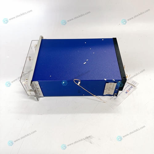
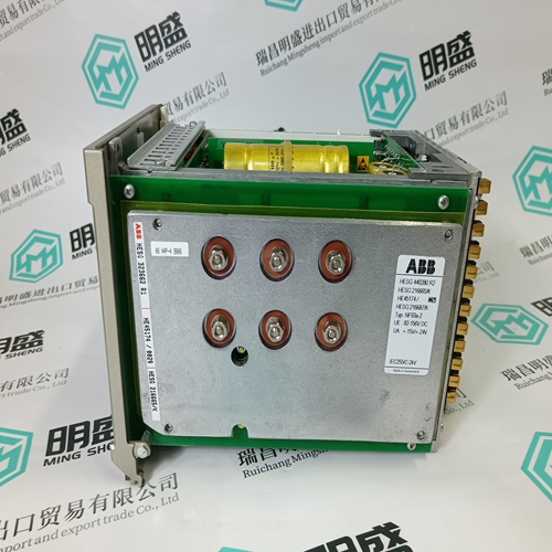
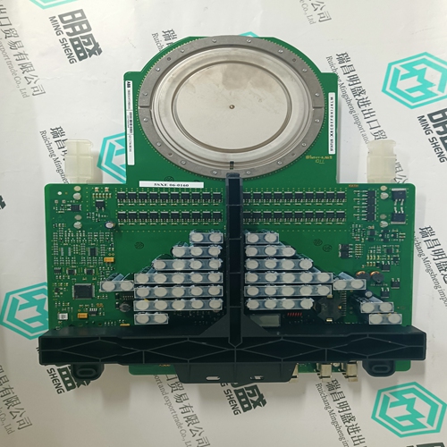
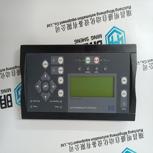
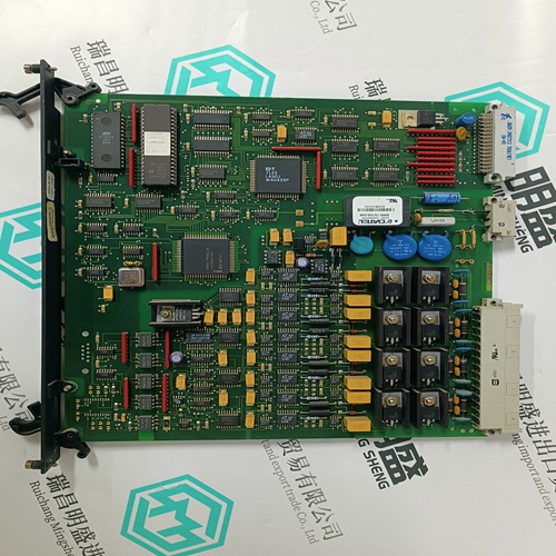
ALSTOM MVTU11K1CD0751G Digital output module
- Product ID: MVTU11K1CD0751G
- Brand: ALSTOM
- Place of origin: The United States
- Goods status: new/used
- Delivery date: stock
- The quality assurance period: 365 days
- Phone/WhatsApp/WeChat:+86 15270269218
- Email:stodcdcs@gmail.com
- Tags:ALSTOMMVTU11K1CD0751GDigital output module
- Get the latest price:Click to consult
ALSTOM MVTU11K1CD0751G Digital output module
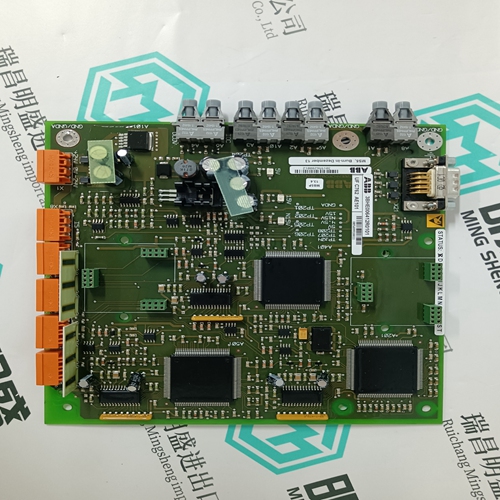
Signals are fed through diodes CR62, CR70, CR63 and CR71 to pin 7. At pin 7, the clock signal and the current signal are combined. C54, C64, C74 and C84 block DC from Q4, Q6, Q8 and Q10 from appearing on pin 7 of each PWM. The duty cycle of the PWM is controlled by comparing the output of the error amplifiers (U15, U16, U17 and U18) to the ramp of the oscillator and the current sense signal of the high frequency transformers. Q5, Q9, Q7 and Q11 make up the soft start. When their bases are pulled low or their emitters are pulled low, the PWM shuts down. When the bases or the emitters are released, the PWMs will slowly widen pulse width and then are controlled by error amps.
SUPERVISORY FUNCTIONS
U14, U11, and U12 and the associated components form the supervisory circuit. These functions include: undervoltage lockout, phase loss detection, overvoltage protection, control failure, inrush current suppression, mode detect and over- temperature lockout. Inrush current limitation and mode detection are implemented by U12. The other functions are implemented by the power supply's supervisor chip U14 (UC3544).


Do you want to know about our products?
We have a large amount of inventory and high quality, out of production control system components, DCS system accessories, robot system accessories, large servo system spare parts. PLC module, DCS module, CPU module, IO module, DO module, AI module, DI module, network communication module, Ethernet module, motion control module, analog input module, analog output module, digital input module, digital output module, redundancy module, power module, relay output module, relay input module, processor module and other major brands.
This article from the temporal Ming sheng automation equipment co., LTD., reproduced please attach this link: http://www.stockdcs.com/
