Home > Product > DCS control system > ABB NWX511a-2R HESG112548R12 Relay input module
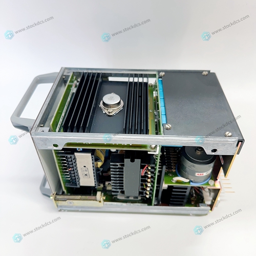
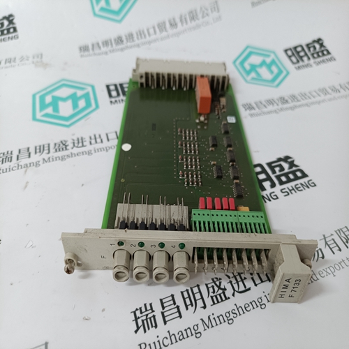
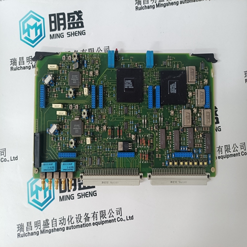
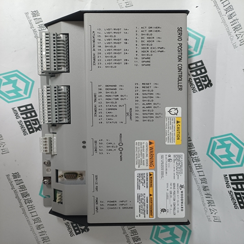
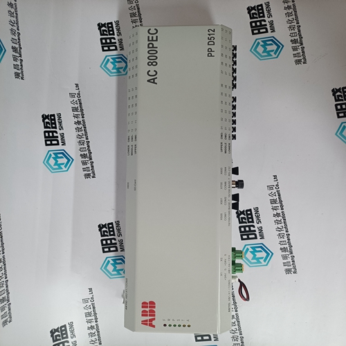
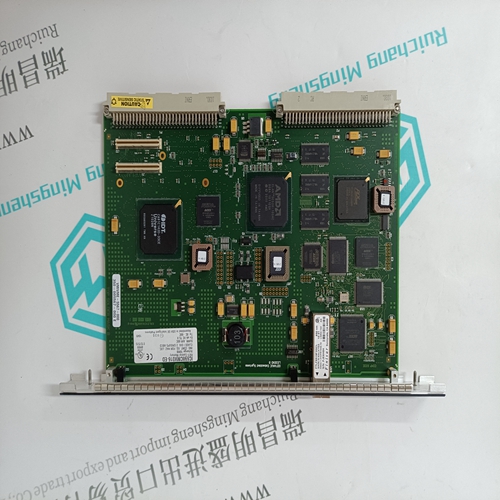
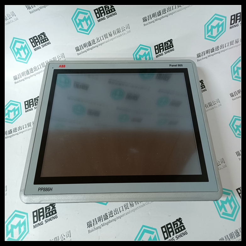
ABB NWX511a-2R HESG112548R12 Relay input module
- Product ID: NWX511a-2R HESG112548R12
- Brand: ABB
- Place of origin: The Swiss
- Goods status: new/used
- Delivery date: stock
- The quality assurance period: 365 days
- Phone/WhatsApp/WeChat:+86 15270269218
- Email:xiamen2018@foxmail.com
- Tags:ABBNWX511a-2RHESG112548R12Relay input module
- Get the latest price:Click to consult
ABB NWX511a-2R HESG112548R12 Relay input module
After the module has been replaced, the following test procedure should be done: A) With no load connected to the output terminals of the power supply, adjust the front panel's Voltage and Current controls fully counter clockwise. B) Apply power. Turn on the front panel CB (supply starts after a ten second delay). Turn up the Current and Voltage controls until the output is about 15% of Max. voltage, then adjust the load for about 20% of Max. current.
A100 CONTROL BOARD
All of the plugs (12 total) on the A100 board should be disconnected before removing the board. Unscrew and remove the six screws which hold the board to the chassis. Remove J1 which is located on the rear panel. The board should now be free of any connections and can be simply removed. Replace in the reverse order and be sure the connectors are correctly plugged back into the PCB. If unsure, mark the connectors before unplugging. A) Rotate the front panel controls fully counter clockwise. B) Apply AC power. Turn on the front panel CB and slowly advance the current control 1/4 turn. Slowly advance the voltage control. The output should gradually increase as the Voltage control is rotated.


Do you want to know about our products?
We have a large amount of inventory and high quality, out of production control system components, DCS system accessories, robot system accessories, large servo system spare parts. PLC module, DCS module, CPU module, IO module, DO module, AI module, DI module, network communication module, Ethernet module, motion control module, analog input module, analog output module, digital input module, digital output module, redundancy module, power module, relay output module, relay input module, processor module and other major brands.
This article from the temporal Ming sheng automation equipment co., LTD., reproduced please attach this link: http://www.stockdcs.com/
