Home > Product > PLC programmable module > NI GPIB-140A/2 total line expander
NI GPIB-140A/2 total line expander
- Product ID: GPIB-140A/2
- Brand: NI
- Place of origin: the United States
- Goods status: new/used
- Delivery date: stock
- The quality assurance period: 365 days
- Phone/WhatsApp/WeChat:+86 15270269218
- Email:stodcdcs@gmail.com
- Tags:NIGPIB-140A/2total line expander
- Get the latest price:Click to consult
The main products
Spare parts spare parts, the DCS control system of PLC system and the robot system spare parts,
Brand advantage: Allen Bradley, BentlyNevada, ABB, Emerson Ovation, Honeywell DCS, Rockwell ICS Triplex, FOXBORO, Schneider PLC, GE Fanuc, Motorola, HIMA, TRICONEX, Prosoft etc. Various kinds of imported industrial parts
Products are widely used in metallurgy, petroleum, glass, aluminum manufacturing, petrochemical industry, coal mine, papermaking, printing, textile printing and dyeing, machinery, electronics, automobile manufacturing, tobacco, plastics machinery, electric power, water conservancy, water treatment/environmental protection, municipal engineering, boiler heating, energy, power transmission and distribution and so on.
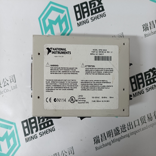
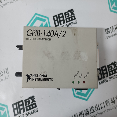
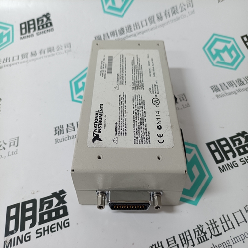
NI GPIB-140A/2 total line expander
2 km, total line expander GPIB - GPIB - 140 - a / 2 GPIB system of wire rope can be extended two thousand meters, and will not affect the integrity of the GPIB, no need to modify the software. The fittings used buffer transmission technology, data transmission rate is as high as 1.1 Mb/s (IEEE 488.1) or 2.8 Mb/s (HS488). GPIB - 140 - a / 2 can also be GPIB system: the maximum number of GPIB equipment increased from 15 to 26.
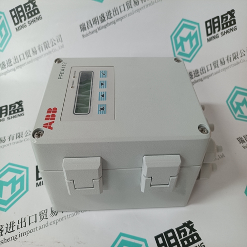
INNIS01 Network Interface
The INNIS01 Network Interface module is the front end of every Cnet communication interface. It is the intelligent link between a node and the Cnet network. In this case, it works in conjunction with the INICT03 module. The INNIS01 module allows any node to communicate with any other node within the Symphony system. The INNIS01 module is a single printed circuit board that occupies one slot in a module mounting unit (MMU). The circuit board contains microprocessor based communication circuitry that enables it to interface with the INICT03 module over a dedicated I/O expander bus. Two latching screws on the faceplate secure the INNIS01 module to the module mounting unit. There are 16 LEDs on the faceplate that display error codes and event/error counts. The INNIS01 module has three card edge connectors for external signals and power (P1, P2, and P3). Connector P1 connects to common and +5, +15, and -15 VDC power. Connector P2 connects the INNIS01 module to the I/O expander bus to communicate with the INICT03 module. The INNIS01 module connects to its Cnet communication network through a cable attached between its P3 connector and an NTCL01 termination unit. Communication between nodes is through coaxial or twinaxial cables that connect the termination units of each node.
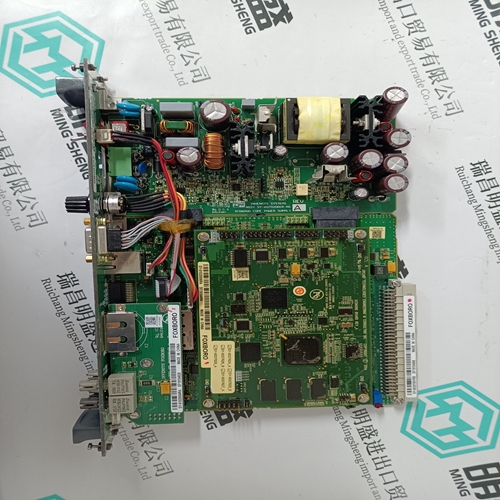
INICT03 Computer Transfer
The INICT03 Computer Transfer module handles all communication with a host computer. The module is command driven through software on the host computer. The INICT03 module receives a command from the host computer, executes it, then replies. The INICT03 module firmware enables the host computer to issue commands for data acquisition, process monitoring, and process control, and to perform system functions such as security, time-synchronization, status monitoring, and module configuration. The INICT03 module can store up to 30,000 point definitions (depending on point types). It uses an IMMPI01 module for host computer connection. The INICT03 module is a single printed circuit board that occupies one slot in the module mounting unit. The circuit board contains microprocessor based communication circuitry that enables it to directly communicate with its INNIS01 module, to directly communicate with an IMMPI01 module, and to interface to Controlway. Two latching screws on the faceplate secure the INICT03 module to the module mounting unit. There are 17 LEDs on the faceplate and a stop/reset pushbutton. The INICT03 module has three card edge connectors for external signals and power (P1, P2, and P3). Connector P1 connects to common, +5 VDC power, and Controlway. Connector P2 connects the INICT03 module to the I/O expander bus to communicate with the INICT03 module. Control and data signals connect from the INICT03 module to the IMMPI01 module through a 60-pin ribbon cable. The cable connects between the INICT03 P5 connector and the IMMPI01 P6 connector.