Home > Product > Robot control system > ALSTOM V4561983-0100 V4559856 Control card
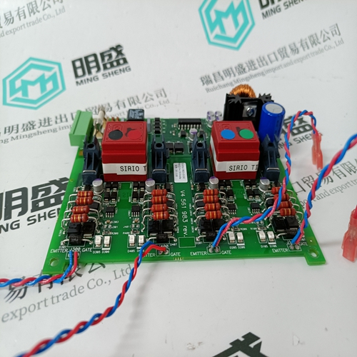
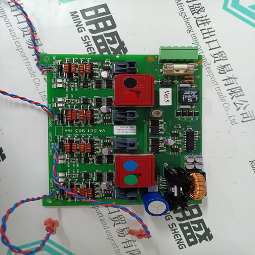
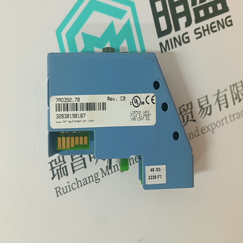
ALSTOM V4561983-0100 V4559856 Control card
- Product ID: V4561983-0100 V4559856
- Brand: ALSTOM
- Place of origin: the United States
- Goods status: new/used
- Delivery date: stock
- The quality assurance period: 365 days
- Phone/WhatsApp/WeChat:+86 15270269218
- Email:stodcdcs@gmail.com
- Tags:ALSTOMV4561983-0100 V4559856Control card
- Get the latest price:Click to consult
The main products
Spare parts spare parts, the DCS control system of PLC system and the robot system spare parts,
Brand advantage: Allen Bradley, BentlyNevada, ABB, Emerson Ovation, Honeywell DCS, Rockwell ICS Triplex, FOXBORO, Schneider PLC, GE Fanuc, Motorola, HIMA, TRICONEX, Prosoft etc. Various kinds of imported industrial parts
Products are widely used in metallurgy, petroleum, glass, aluminum manufacturing, petrochemical industry, coal mine, papermaking, printing, textile printing and dyeing, machinery, electronics, automobile manufacturing, tobacco, plastics machinery, electric power, water conservancy, water treatment/environmental protection, municipal engineering, boiler heating, energy, power transmission and distribution and so on.
ALSTOM V4561983-0100 V4559856 Control card
Pole two enables or disables ROM checksumming. Elsag Bailey recommends that the INNIS01 module be installed with checksumming enabled to take full advantage of the on-board diagnostics. Pole 3/4 Pole three enables internal testing which must be disabled for normal operation. Pole four, in conjunction with pole three, makes the node appear to be busy to other nodes. This condition is used by Elsag Bailey personnel only. Pole 5 Pole five enables the channel idle condition display for the front panel LEDs. If channel one is idle, the group A LEDs will flash on and off about twice per second. If channel two is idle, the group B LEDs will flash. The channel idle display is intended to serve as a warning that a loop integrity problem exists. Pole 6 Pole six enables diagnostic tests that preclude normal INNIS01 module operation. Pole 7/8 Poles seven and eight determine loop speed and loop mode. NOTE: Testing modes involving poles three, four, and six interfere with normal operation. Dipswitch SW4 - I/O Module Address and Counters The INNIS01 module can have an I/O expander bus address from zero to seven. Poles one through three of dipswitch SW4 set the I/O expander bus address of the module. Refer to Table 3-4 for I/O expander bus address settings. Poles four through eight set the address of the on-board event and error counters that the INNIS01 module displays using the group A and B faceplate LEDs. LED B8 is the most significant bit. LED A1 is the least significant bit. Table 3-5 lists the possible event counter addresses. Table 3-6 lists the possible error counter addresses. Record the dipswitch SW4 settings in the space provided.
Jumper Settings
There are six jumpers on the INNIS01 module that set the communication rate of the receiver analog circuit (refer to Figure 3-2 for jumper locations). All six jumpers must be set in the same position. Jumper setting instructions are silk screened on the upper left corner of the INNIS01 circuit board. The jumper setting must match the communication rate set by poles seven and eight of dipswitch SW3. Figure 3-3 shows which pins to jumper for various network modes. This figure shows placement of the pins when looking at the top of the INNIS01 circuit board with the faceplate on the left.If the INNIS01 dipswitches and jumpers are properly configured, it is ready to be installed in the module mounting unit. Refer to Figure 3-1 for cable connections. To install the module: 1. Verify the module slot assignment in the module mounting unit. 2. Verify that a 24-pin dipshunt is installed in the I/O expander bus sockets between the MMU slot to be used by the INNIS01 module and the slot to be used by the INICT03 module.3. Remove any 24-pin dipshunts from the I/O expander bus sockets that would connect the INNIS01 module to any module other than the INICT03 and IMMPI01 modules. 4. Attach the hooded end of the NKLS01 or NKLS11 cable to the MMU backplane cable connector opening for the INNIS01 module. 5. Slide the INNIS01 module in while guiding the top and bottom edges of the circuit board along the top and bottom rails of the module mounting unit. 6. Push on the faceplate until the rear edge of the module is firmly seated in the backplane connector. 7. Turn the two latching screws ½-turn to lock the module in place. The module is locked into place when the open side of the slot on the latching screws faces the center of the faceplate. Refer to the NTCL01 termination unit instruction for complete termination device information. Appendix A provides quick reference information about the termination unit.