Home > Product > Gas turbine system > V7768-322001 combustion engine card
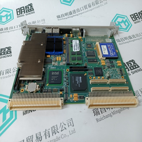
V7768-322001 combustion engine card
- Product ID: V7768-322001
- Brand: GE
- Place of origin: the United States
- Goods status: new/used
- Delivery date: stock
- The quality assurance period: 365 days
- Phone/WhatsApp/WeChat:+86 15270269218
- Email:stodcdcs@gmail.com
- Tags:V7768-322001combustion engine card
- Get the latest price:Click to consult
The main products
Spare parts spare parts, the DCS control system of PLC system and the robot system spare parts,
Brand advantage: Allen Bradley, BentlyNevada, ABB, Emerson Ovation, Honeywell DCS, Rockwell ICS Triplex, FOXBORO, Schneider PLC, GE Fanuc, Motorola, HIMA, TRICONEX, Prosoft etc. Various kinds of imported industrial parts
Products are widely used in metallurgy, petroleum, glass, aluminum manufacturing, petrochemical industry, coal mine, papermaking, printing, textile printing and dyeing, machinery, electronics, automobile manufacturing, tobacco, plastics machinery, electric power, water conservancy, water treatment/environmental protection, municipal engineering, boiler heating, energy, power transmission and distribution and so on.
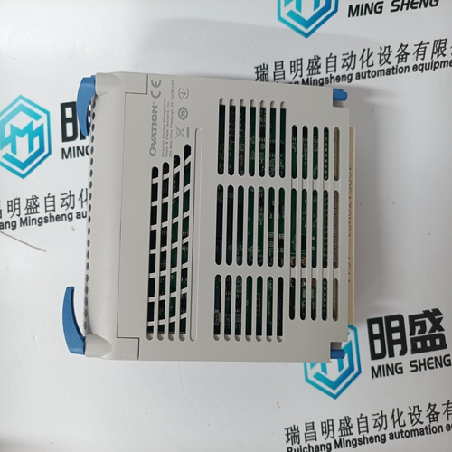
V7768-322001 combustion engine card
The communication system provides a means to monitor the status of the power system of each node. This status information can be displayed on a human system interface. Electronics within the power entry panel monitor the power system status. A single status output is made available to the communication system. To use this feature, wire the status output to the terminal block on the NTCL01 termination unit labeled PSS1 or PSS2. Two sets of terminals are available on the termination unit for interconnecting the power system status output. This power system status signal is fed through the termination unit cable to the P3 connector on the INNIS01 module. The power system status input is a TTL-compatible signal. A high voltage level (5 VDC) on power system status indicates good status. A low voltage level (0 VDC) indicates bad status. When no connection is made to either of the power system status inputs, a pull-up resistor on the INNIS01 module causes a high level signal on the power system status input, thereby reporting good status.
INICT03 Computer Transfer
The Cnet-to-computer interface requires an INICT03 Computer Transfer module. Dipswitches, jumpers, and a dispshunt must be set before putting the module into operation. Figure 3-4 shows the dipswitch and jumper locations on the module. NOTE: This module uses connections to the MMU backplane that served other functions in earlier Network 90® systems. To avoid potential module damage, evaluate your system for compatibility prior to module installation. Early Network 90 systems applied -30 VDC to pins three and four of the module connector P1. This voltage is not required for Symphony and INFI 90 OPEN modules. In Symphony and INFI 90 OPEN systems, pin four is used for the Controlway bus. If your system contains modules that require -30 VDC, set jumper J5 to the 30 VDC position. Doing so allows the installation of the INICT03 module in a module mounting unit that uses -30 VDC and limits communication to module bus.Dipswitch SW1 UMB1 is an eight pole dipswitch that sets the serial port (RS-232-C) communication rate. The communication rate directly affects data throughput. Refer to Table 3-7 for communication rates. Record the dipswitch SW1 UMB1 settings in the space provided.