Home > Product > PLC programmable module > BENTLY 3500/45 Pressure monitor
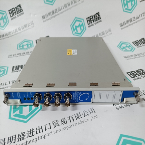
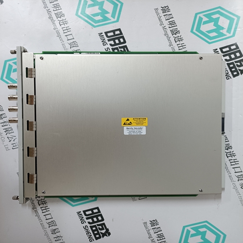
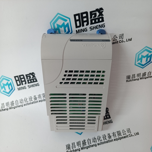
BENTLY 3500/45 Pressure monitor
- Product ID: 3500/45
- Brand: BENTLY
- Place of origin: the United States
- Goods status: new/used
- Delivery date: stock
- The quality assurance period: 365 days
- Phone/WhatsApp/WeChat:+86 15270269218
- Email:stodcdcs@gmail.com
- Tags:BENTLY 3500/45Pressure monitor
- Get the latest price:Click to consult
The main products
Spare parts spare parts, the DCS control system of PLC system and the robot system spare parts,
Brand advantage: Allen Bradley, BentlyNevada, ABB, Emerson Ovation, Honeywell DCS, Rockwell ICS Triplex, FOXBORO, Schneider PLC, GE Fanuc, Motorola, HIMA, TRICONEX, Prosoft etc. Various kinds of imported industrial parts
Products are widely used in metallurgy, petroleum, glass, aluminum manufacturing, petrochemical industry, coal mine, papermaking, printing, textile printing and dyeing, machinery, electronics, automobile manufacturing, tobacco, plastics machinery, electric power, water conservancy, water treatment/environmental protection, municipal engineering, boiler heating, energy, power transmission and distribution and so on.
BENTLY 3500/45 Pressure monitor
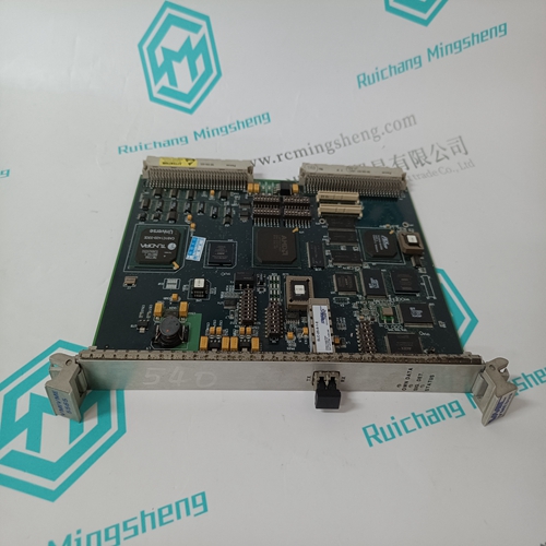
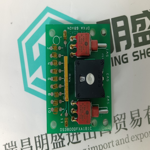
Dipswitch SW2 LMB2 selects certain operating options and enables diagnostics that are meaningful to qualified Elsag Bailey service personnel (refer to Table 3-8). All poles on dipswitch SW2 LMB2 must be closed (on) for normal operation.Dipswitch SW3 LLB3 enables or disables the SCSI port and sets the SCSI port address. Table 3-9 shows the dipswitch settings. If the SCSI port is enabled, serial port one is disabled. Record the dipswitch SW3 LLB3 settings in the space provided. Table 3-8. Dipswitch SW2 LMB2 (INIIT03) Pole Setting Function 1 1 INNIS01 handshake time-out disabled. 0 INNIS01 handshake time-out enabled; normal operation. 2 1 INNIS01 module diagnostics enabled. 0 INNIS01 module diagnostics disabled; normal operation. 3 1 Cnet/INFI-NET diagnostics enabled. 0 Cnet/INFI-NET diagnostics disabled; normal operation. 4 1 Hardware diagnostics enabled. 0 Hardware diagnostics disabled; normal operation. 5 - 8 0 Not used. NOTE: 1 = open or off, 0 = closed or on. Table 3-9. Dipsw There are four jumpers (jumper J1, J2, J4, and J5) on the INICT03 module. These jumpers are for special INICT03 hardware applications. They define the RS-232-C diagnostic port as data terminal equipment (DTE) or data communication equipment (DTE), define the type of SRAM contained on the SRAM modules, enable the machine fault timer, and enable the module to operate in a module mounting unit that uses -30 VDC. Refer to Table 3-11 for the jumper settings.
Multifunction Processor Interface
The Cnet-to-computer interface requires an IMMPI01 Multifunction Processor Interface module. The IMMPI01 module provides the INICT03 module with two serial ports and a SCSI parallel port. A 60-pin ribbon cable connects the IMMPI01 module to the INICT03 module. Jumpers must be set before putting the module into operation. Figure 3-5 shows the jumper locations on the module. IMMPI01 Jumper Settings The IMMPI01 module has two sets of jumpers that select handshake signal types: request to send (RTS) or clear to send (CTS). These signals leave the module through a cable connection to the NTMP01 termination unit. Jumpers J1 and J2 must be set as shown in Figures 3-6 and 3-7. INICT03 and IMMPI01 Module Installation If the INICT03 and IMMPI01 modules are properly configured, they are ready to be installed in the module mounting unit.30 VDC Pre-Installation Check To determine if the module mounting unit uses -30 VDC: 1. Locate the -30 VDC faston. It is the second faston from the top when viewing the module mounting unit from the rear. 2. Check for -30 VDC with respect to system common at the -30 VDC faston. 3. If -30 VDC is present, set the Jumper J5 of the INICT03 module to the appropriate positions. Installation To install the INICT03 and IMMPI01 modules: 1. Verify the INICT03 and IMMPI01 module slot assignments (INICT03 module in the right slot, IMMPI01 module in the left slot) in the module mounting unit are adjacent to its associated INNIS01 module. 2. Connect one end of the 60-pin ribbon cable to connector P5 on the INICT03 module (Fig. 3-1).
