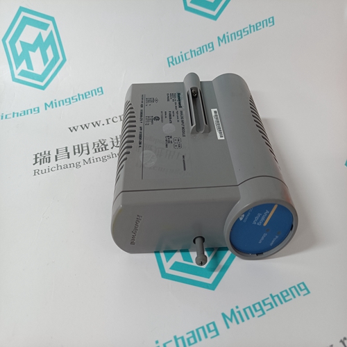
Home > Product > Robot control system > ABSOLUTE API4380G Signal transmitter
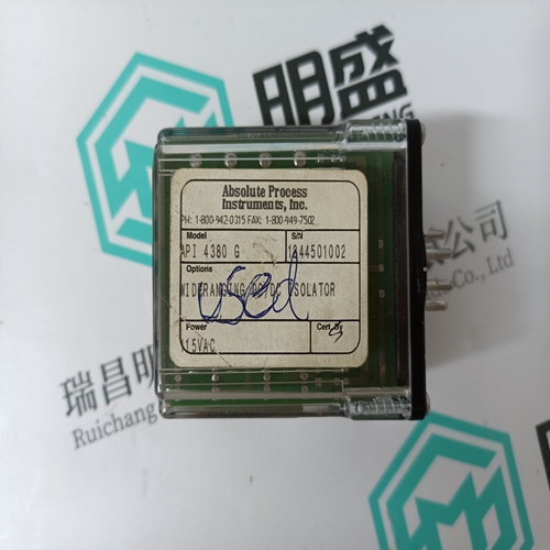
ABSOLUTE API4380G Signal transmitter
- Product ID: API4380G
- Brand: ABSOLUTE
- Place of origin: the United States
- Goods status: new/used
- Delivery date: stock
- The quality assurance period: 365 days
- Phone/WhatsApp/WeChat:+86 15270269218
- Email:stodcdcs@gmail.com
- Tags:ABSOLUTEAPI4380GSignal transmitter
- Get the latest price:Click to consult
The main products
Spare parts spare parts, the DCS control system of PLC system and the robot system spare parts,
Brand advantage: Allen Bradley, BentlyNevada, ABB, Emerson Ovation, Honeywell DCS, Rockwell ICS Triplex, FOXBORO, Schneider PLC, GE Fanuc, Motorola, HIMA, TRICONEX, Prosoft etc. Various kinds of imported industrial parts
Products are widely used in metallurgy, petroleum, glass, aluminum manufacturing, petrochemical industry, coal mine, papermaking, printing, textile printing and dyeing, machinery, electronics, automobile manufacturing, tobacco, plastics machinery, electric power, water conservancy, water treatment/environmental protection, municipal engineering, boiler heating, energy, power transmission and distribution and so on.
ABSOLUTE API4380G Signal transmitter
Verify that a 24-pin dipshunt is installed in the I/O expander bus sockets between the module mounting unit slot to be used by the INNIS01 module and the slots to be used by the INICT03 and IMMPI01 modules. When installing the computer interface modules, there must be continuity between the INNIS01 and INICT03 modules. Observe the following: • Install one dipshunt in the I/O expander bus socket between the INNIS01 slot and INICT03 slot if the INNIS01 module is mounted to the right of the INICT03/IMMPI01 combination. • If the INNIS01 module is mounted to the left of the INICT03/IMMPI01 combination, two dipshunts are required. Install one dipshunt between the INNIS01 slot and IMMPI01 slot. Install the second dipshunt between the IMMPI01 slot and the INICT03 slot. 5. Remove any 24-pin dipshunts from the I/O expander bus sockets that would connect the INICI03 interface modules to any module other than those making up the interface. 6. Attach the hooded end of the NKTU01 or NKTU11 cable to the module mounting unit backplane cable connector opening for the IMMPI01 module. The other end of the cable attaches to the NTMP01 termination unit. 7. Slide the INICT03 and IMMPI01 modules in while guiding the top and bottom edges of the circuit boards along the top and bottom rails of the module mounting unit. 8. Push on the faceplate until the rear edges of the modules are firmly seated in the backplane connectors.
Introduction
After completing the steps detailed in the installation section, the Cnet-to-computer interface modules are ready to be put into operation. This section provides the necessary information for daily operation of the modules.the firmware to execute self-diagnostic routines. The INICT03 module determines when the INNIS01 module will go online. The INNIS01 module comes online in the network mode set by poles seven and eight of dipswitch SW3, with the type of counter display set by poles four through eight of dipswitch SW4. Use the counter display (faceplate LEDs) to check the INNIS01 module operation. If communication errors occur, the host module sets the INNIS01 module communication status bits in the module status. View the module status by using a human system interface. Event Counters Internal counters maintain a count of events such as the number of messages transmitted, retries, and number of messages lost. Table 3-5 has a complete list of event counters. The group A and B LEDs on the module faceplate display a binary value of the event counters (LED B8 is the most significant bit, LED A1 is the least significant bit). Figure 4-1 shows the location of the group A and group B LEDs.
