Home > Product > DCS control system > 1C31222G01 analog output module
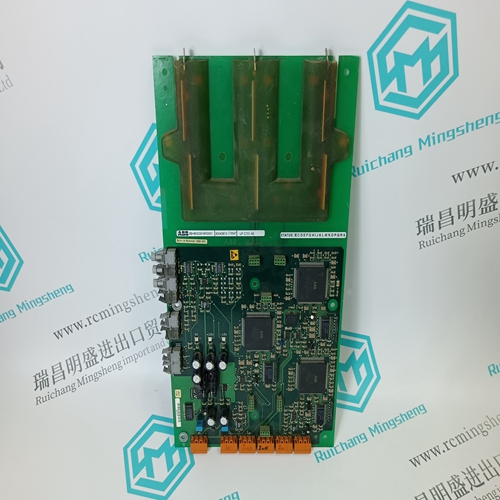
1C31222G01 analog output module
- Product ID: 1C31222G01
- Brand: EMERSON
- Place of origin: The United States
- Goods status: new/used
- Delivery date: stock
- The quality assurance period: 365 days
- Phone/WhatsApp/WeChat:+86 15270269218
- Email:stodcdcs@gmail.com
- Tags:1C31222G01analog output module
- Get the latest price:Click to consult
The main products
Spare parts spare parts, the DCS control system of PLC system and the robot system spare parts,
Brand advantage: Allen Bradley, BentlyNevada, ABB, Emerson Ovation, Honeywell DCS, Rockwell ICS Triplex, FOXBORO, Schneider PLC, GE Fanuc, Motorola, HIMA, TRICONEX, Prosoft etc. Various kinds of imported industrial parts
Products are widely used in metallurgy, petroleum, glass, aluminum manufacturing, petrochemical industry, coal mine, papermaking, printing, textile printing and dyeing, machinery, electronics, automobile manufacturing, tobacco, plastics machinery, electric power, water conservancy, water treatment/environmental protection, municipal engineering, boiler heating, energy, power transmission and distribution and so on.
1C31222G01 analog output module
General Cleaning and Washing If the printed circuit board needs minor cleaning: Remove dust and residue from the printed circuit board surface using clean, dry, filtered compressed air or an antistatic field service vacuum cleaner. Another method of washing the printed circuit board is: 1. Clean the printed circuit board by spraying it with isopropyl alcohol (99.5% electronic grade) or wiping the board with a foam-tipped swab wetted in isopropyl alcohol. 2. When the circuit board is clean, remove excess solvent by using compressed air to blow it free of the circuit board. Edge Connector Cleaning To clean edge connector contacts: 1. Use a solvent mixture of 80% isopropyl alcohol (99.5% electronic grade) and 20% distilled water. 2. Soak a lint-free cloth with the solvent mixture. 3. Work the cloth back and forth parallel to the edge connector contacts. 4. Repeat with a clean cloth that is soaked with the solvent mixture. 5. Dry the edge connector contact area by wiping with a clean lint-free cloth.To clean tarnished or deeply stained edge connector contacts: 1. Use an Eberhard Faber (400A) pink pearl eraser, or equivalent to remove tarnish or stains. Fiberglass or nylon burnishing brushes may be used also. 2. Minimize electrostatic discharge by using the 80/20 isopropyl alcohol and water solution during burnishing. 3. Do not use excessive force while burnishing. Use only enough force to shine the contact surface. Inspect the edge connector after cleaning to assure no loss of contact surface.
Checking Connection
Check all signal wiring, power and ground connections within the cabinet to verify their integrity. When checking connections, always turn a screw, nut or other fastening device in the direction to tighten only. If the connection is loose, it will be tightened. If the connection is tight, the tightening action will verify that it is secure. There must not be any motion done to loosen the connection. NOTE: Power to the cabinet must be off while performing this preventive maintenance task. Check and verify that all cable connections are secure.
This section explains repair and replacement procedures for Cnet-to-computer interface modules. There are no special tools required to replace any of the modules. Repair Repair procedures are limited to module replacement. If a module fails, remove and replace it with another. Verify that the replacement module dipswitch and jumper settings are the same as those of the failed module. NOTE: Do not remove the INICT03 module under power unless the stop/reset pushbutton has been depressed and module operation has been halted. Module Replacement The following steps describe module replacement. Observe the steps listed under Special Handling in Section 3 when handling interface modules. 1. Press the stop/reset pushbutton if the module is not already halted. 2. Turn the two latching screws on the defective interface module ½-turn either way to release it. NOTE: The INICT03 and IMMPI01 modules are connected by ribbon cable. Both modules must be removed and disconnected. 3. Grasp the screws and slide out the module (or modules). 4. If necessary, disconnect the cable connecting the modules and replace only the defective module. 5. Set any dipswitches and jumpers on the replacement module to match the settings of the removed module. 6. If necessary, connect the replacement module with any interconnecting modules.