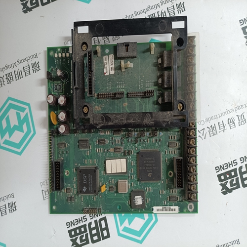
Home > Product > PLC programmable module > ICS TRIPLEX 9832*3 base module
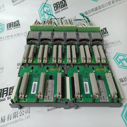
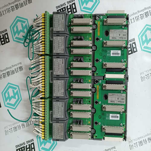
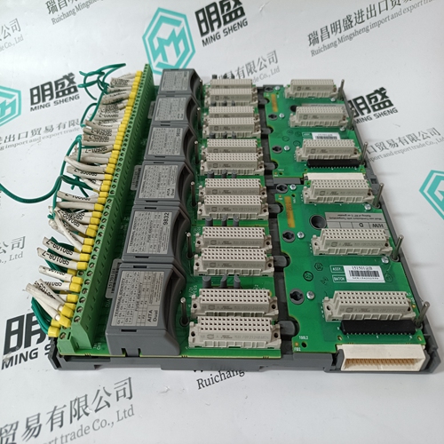
ICS TRIPLEX 9832*3 base module
- Product ID: 9832*3
- Brand: ICS TRIPLEX
- Place of origin: the United States
- Goods status: new/used
- Delivery date: stock
- The quality assurance period: 365 days
- Phone/WhatsApp/WeChat:+86 15270269218
- Email:stodcdcs@gmail.com
- Tags:ICS TRIPLEX9832*3base module
- Get the latest price:Click to consult
The main products
Spare parts spare parts, the DCS control system of PLC system and the robot system spare parts,
Brand advantage: Allen Bradley, BentlyNevada, ABB, Emerson Ovation, Honeywell DCS, Rockwell ICS Triplex, FOXBORO, Schneider PLC, GE Fanuc, Motorola, HIMA, TRICONEX, Prosoft etc. Various kinds of imported industrial parts
Products are widely used in metallurgy, petroleum, glass, aluminum manufacturing, petrochemical industry, coal mine, papermaking, printing, textile printing and dyeing, machinery, electronics, automobile manufacturing, tobacco, plastics machinery, electric power, water conservancy, water treatment/environmental protection, municipal engineering, boiler heating, energy, power transmission and distribution and so on.
ICS TRIPLEX 9832*3 base module
The INNIS01 Network Interface Module is the front end of every Cnet communication interface. It is the intelligent link between a node and the Cnet. In this case, it works in conjunction with the INICT12 module. The INNIS01 module allows any node to communicate with any other node within the Symphony system The INNIS01 module is a single printed circuit board that occupies one slot in a module mounting unit (MMU). The circuit board contains microprocessor based communication circuitry that enables it to interface with Cnet, and with the INICT12 module over a dedicated I/O expander bus segment. Two latching screws on the faceplate secure the INNIS01 module to the module mounting unit (Fig. 2-2). There are 16 LEDs on the faceplate that display event or error counts and error codes.The INNIS01 module has three card edge connectors for external signals and power (P1, P2, and P3). P1 connects to common and +5, +15, and -15 VDC power. P2 connects the INNIS01 module to the I/O expander bus to communicate with its INICT12 module. P3 connects the module to its NTCL01 communication termination unit. Communication between Cnet nodes is through coaxial or twinaxial cable that connects between the termination units of each node. An NTCL01 unit provides the redundant Cnet connection points for the INICI12 interface node (coaxial J1 through J4 or twinaxial TB1 and TB2). The INNIS01 module connects to the NTCL01 unit through an NKLS01 or NKLS11 cable attached between its P3 connector and P1 on the termination unit. The termination unit provides isolation circuitry for Cnet.
Block Diagram
Figure 2-3 is a functional block diagram of the INNIS01 module. The module contains a central processing unit (CPU), memory, I/O expander bus interface, and a Cnet interface that supports redundant Cnet (loop one and loop two)he CPU contains a 32-bit microprocessor running at 10 megahertz and associated support circuitry (i.e., control logic, address decoder, buffer control, etc.). The CPU interprets and executes instructions to control communication and run diagnostics. Since the microprocessor is responsible for overall module operation, it communicates with all the functional blocks.
The INNIS01 module handles all Cnet communication for the INICI12 interface. This includes transmitting Cnet messages originated from the node, receiving messages intended for the node, and forwarding Cnet messages destined for other Cnet nodes. The Cnet interface contains a transceiver, loop one and loop two transmit drivers, and loop one and loop two receivers. The INNIS01 module has the ability to isolate itself from Cnet in the event of a component failure or to perform diagnostics. NOTE: The INNIS01 module supports INFI-NET communication in existing INFI 90 OPEN systems. Receive On the receive side, the module has two independent channels with separate memory for each channel to temporarily store incoming messages. Messages are received on both channels simultaneously and stored. The data is automatically checked for integrity and various data protocol errors. I
